
Decoding the 60V Electric Scooter Controller Wiring Diagram PDF
Upgrading or building a high-performance Personal Electric Vehicle (PEV) in 2026 almost inevitably leads you to a 60V architecture. A true 60V system utilizes a 16S Lithium-ion battery pack (59.2V nominal, 67.2V fully charged) or a 20S LiFePO4 setup. The brain of this system is the motor controller, and understanding the manufacturer's 60v electric scooter controller wiring diagram pdf is the difference between a flawless build and a catastrophic MOSFET failure.
Whether you are installing a generic KT6036X square-wave controller (typically priced around $75) or a premium FOC (Field Oriented Control) unit like the VOTOL EM-100 (around $210), the fundamental wiring topology remains consistent. This step-by-step walkthrough dissects the standard PDF wiring schematics provided by PEV manufacturers, translating confusing color codes into actionable, safe wiring procedures.
Prerequisites and Tool Selection
Before cutting a single wire, ensure your workstation is equipped to handle high-current DC applications. Soldering 8 AWG silicone wire requires a high-thermal-mass iron. A standard 60W iron will struggle, leading to cold solder joints that increase resistance and generate excessive heat under load.
- Soldering Station: Pinecil V2 (set to 380°C) or Hakko FX-888D with a large chisel tip (e.g., T18-D24).
- Wire Strippers: Precision automatic strippers for 18-24 AWG, and heavy-duty flush cutters for 8-10 AWG.
- Multimeter: A true-RMS digital multimeter to verify the 5V hall sensor logic lines and throttle signal voltages.
- Heat Shrink: 3:1 shrink ratio tubing with adhesive lining for waterproofing phase wire connections.
Wire Gauge Selection for 60V Systems
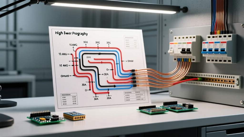
The most common mistake DIY builders make when following a 60v electric scooter controller wiring diagram pdf is undersizing the main power and phase wires. According to the Engineering Toolbox wire ampacity standards, you must account for peak current draws, which can briefly exceed 200% of the continuous rating during hard acceleration.
| Wire Gauge (AWG) | Continuous Current Rating | Peak Current (10 sec) | Recommended Application |
|---|---|---|---|
| 8 AWG Silicone | 45A - 55A | 120A | Main Battery to Controller (B+ / B-) |
| 10 AWG Silicone | 30A - 35A | 90A | Controller to Motor Phase Wires |
| 12 AWG Silicone | 20A - 25A | 60A | High-Current Accessories (DC-DC Converters) |
| 18 AWG PVC | 5A - 7A | 15A | Ignition, Headlights, Brake Cut-offs |
| 22 AWG PVC | 2A - 3A | 5A | Hall Sensors, Throttle Signal, UART Data |
Step 1: Main Power and Ground (The Heavy Wires)
The thickest wires on your controller diagram are the main power (usually Red) and main ground (usually Black). These connect directly to your 60V battery pack's XT90 or QS8 connector.
The Anti-Spark Requirement
Never wire a 60V controller directly to a standard switch or basic connector without an anti-spark mechanism. When you connect a 67.2V fully charged battery to a controller with large internal filter capacitors (typically 100V rated, 1000µF), the inrush current can exceed 300A for a few milliseconds. This arc will pit your connectors and can instantly blow the controller's main capacitors or rectifier diodes.
Critical Safety Warning: Always use an XT90-S anti-spark connector, or wire a 100-ohm, 5W pre-charge resistor in parallel with your main ignition switch. This allows the capacitors to charge slowly before the main contacts close.
Step 2: Phase Wires and Hall Sensors (The Motor Interface)
Brushless DC (BLDC) motors rely on precise electronic commutation. As detailed in the Electrical Easy BLDC motor guide, the controller must know the exact rotor position to fire the correct phase wires. This is achieved through the phase wires and the hall sensor array.
Phase Wires (Yellow, Green, Blue)
Use 10 AWG silicone wire for the phase connections. Keep these wires as short as physically possible—ideally under 12 inches. Long phase wires increase inductance, which causes voltage spikes (back-EMF) when the MOSFETs switch off. These spikes can exceed the 100V breakdown limit of your controller's transistors, resulting in a shorted phase and a locked rear wheel.
Hall Sensor Harness (5-Pin JST-SM)
The hall sensor plug contains five 22 AWG wires:
- Red (+5V): Powers the internal hall effect ICs. Never short this to ground, or you will fry the controller's internal 5V voltage regulator.
- Black (GND): Logic ground.
- Yellow, Green, Blue (Signals): Digital outputs that pulse between 0V and 5V as the motor magnets pass the sensors.
Edge Case - 60° vs 120° Hall Angles: Most modern 60V scooter motors use a 120-degree electrical hall sensor spacing. If your PDF diagram mentions a 'learning wire' (usually a white or yellow loop), connect it to itself to force the controller to auto-detect the hall angle. If the motor stutters violently upon throttle application, your hall angle is mismatched, or one of the signal wires has a broken continuity.
Step 3: Low Voltage Control Signals
The low-voltage harness is where the rider interfaces with the controller. Referencing your specific PDF diagram, locate the following standard pinouts:
Throttle Input (3-Pin Connector)
- Red: +5V reference.
- Black: Signal Ground.
- White/Green: Signal return (0.8V at rest, 4.2V at full throttle). Use your multimeter to verify the throttle outputs exactly 0.8V before connecting it to the controller. A throttle stuck at 1.5V will cause the scooter to launch unexpectedly upon power-up.
Ignition / Lock Wire (Thin Red)
This wire wakes up the controller's internal logic board. It must be routed through a keyswitch or DC-DC converter ignition circuit to the main positive battery terminal. It draws less than 50mA but is strictly required to turn the system on.
Brake Cut-offs (2-Pin Connectors)
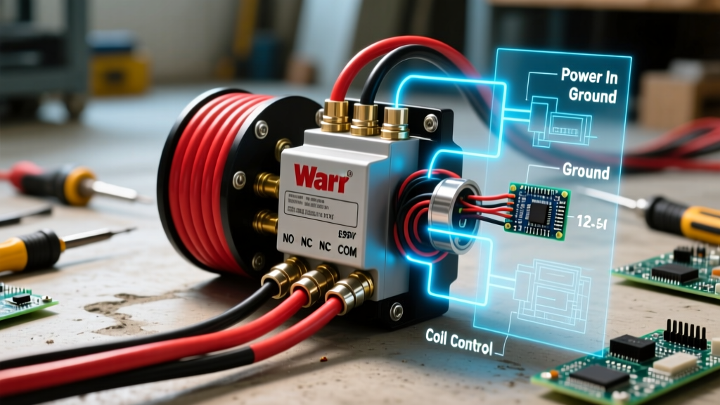
These are simple normally-open (NO) or normally-closed (NC) switches. Most generic 60V PDFs default to Low-Level braking (pulling the signal wire to ground engages the brake cut-off). If your hydraulic brakes have built-in sensors, ensure they match the controller's logic level; otherwise, the motor will remain permanently disabled.
Step 4: Accessories and DC-DC Conversion
A 60V battery will instantly destroy standard 12V scooter headlights and horns. Your wiring diagram will likely show an optional DC-DC converter step-down module. When wiring a 60V-to-12V buck converter:
- Connect the high-voltage input directly to the controller's main power terminals (post-fuse), not to the thin ignition wire.
- Use 12 AWG wire for the 12V output if you are running high-draw LED light bars (e.g., 40W+).
- Ensure the converter is rated for at least 75V input to handle the 67.2V peak charge voltage plus inductive ringing.
Troubleshooting Common Wiring Failures
Even with a perfect 60v electric scooter controller wiring diagram pdf in hand, real-world builds encounter issues. Here is how to diagnose the most frequent 2026 PEV build failures:
Symptom: Controller gets excessively hot at low speeds
Cause: Phase wire inductance or incorrect hall sensor timing. If the controller is firing the phases slightly late due to a damaged hall sensor wire, the motor operates at a severe efficiency loss, dumping excess current as heat into the controller's MOSFETs rather than converting it to mechanical motion.
Symptom: Error Code 07 or 'Hall Fault' on Display
Cause: The controller is not seeing the 5V return signal from one or more hall sensors. Unplug the motor harness and use a multimeter to probe the controller-side plug. You must read exactly 5.0V between the Red and Black pins. If you read 0V, the controller's internal 5V LDO regulator has failed, usually due to a shorted motor harness rubbing against the frame.
Symptom: XT90 connector melts during hard acceleration
Cause: Undersized main wires or a degraded connector. A genuine 60V system pulling 40A continuous requires pristine solder joints. If you used crimp connectors for the 8 AWG wire instead of soldering, the increased contact resistance will generate enough heat to melt the plastic housing of the battery connector.
Final Verification Checklist
Before your maiden voyage, complete this final verification sequence:
- Verify battery voltage at the controller's main terminals (should read ~59V - 67V).
- Turn on the ignition switch; verify the display powers up and shows no error codes.
- Lift the rear wheel off the ground.
- Apply 10% throttle; listen for smooth, quiet motor commutation.
- Engage both brake levers; verify the throttle response is instantly killed.
- Inspect all phase wire heat-shrink joints for physical clearance against the motor casing and swingarm.
By treating the manufacturer's PDF not just as a suggestion, but as a strict electrical blueprint, your 60V electric scooter build will deliver reliable, high-torque performance for years to come.