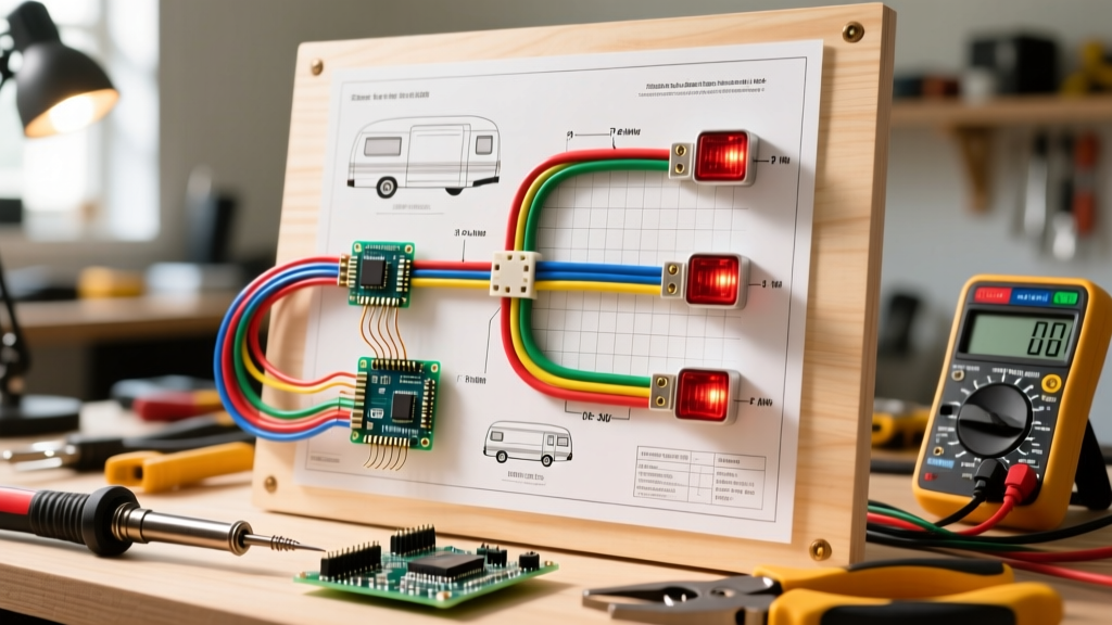

Introduction to Trailer Tail Light Circuitry
When approaching a wiring diagram for tail lights on a trailer or recreational vehicle, it is highly effective to adopt an appliance wiring tutorial mindset. Just as you would trace the control board of a modern HVAC unit or map the compressor circuit of a commercial refrigerator, a trailer lighting harness is a closed-loop DC electrical system. It demands rigorous attention to load calculations, voltage drop mitigation, and proper termination. Whether you are wiring a simple 4x8 utility trailer or a complex 30-foot fifth-wheel RV, understanding the underlying schematic is critical for safety and legal compliance.
As of 2026, the shift toward multiplexed CAN-bus trailer systems and high-efficiency LED arrays has changed how we calculate amperage draws, but the foundational DC principles remain identical. According to the National Highway Traffic Safety Administration (NHTSA), proper lighting and conspicuity are not just recommendations; they are federally mandated under FMVSS 108 to prevent rear-end collisions. In this comprehensive guide, we will break down the standard wiring diagrams, wire gauge requirements, and appliance-grade termination techniques required for a bulletproof trailer lighting system.
Decoding the Standard 4-Way Flat Wiring Diagram
The 4-way flat connector is the industry standard for light-duty utility, boat, and small cargo trailers. It handles the essential lighting circuits required by the Federal Motor Carrier Safety Administration (FMCSA) for basic road legality. When reviewing the wiring diagram for tail lights in this configuration, you are dealing with four distinct pathways: one ground and three power circuits.
| Pin Position | SAE Wire Color | Circuit Function | Incandescent Draw | LED Draw (2026 Std) |
|---|---|---|---|---|
| Pin 1 (Exposed) | White | Chassis Ground | N/A | N/A |
| Pin 2 | Brown | Tail / Running Lights | 4.0A - 6.0A | 0.5A - 1.0A |
| Pin 3 | Yellow | Left Turn / Stop | 2.0A - 4.0A | 0.8A - 1.5A |
| Pin 4 | Green | Right Turn / Stop | 2.0A - 4.0A | 0.8A - 1.5A |
The Grounding Imperative
In appliance wiring, a floating neutral or poor ground will cause a control board to fault. In trailer wiring, a poor ground (Pin 1) causes "backfeeding." This occurs when current from the turn signal circuit seeks an alternate path to ground, traveling backward through the tail light filament and illuminating the running lights on the opposite side of the trailer. Always run a dedicated 12 AWG or 14 AWG white ground wire directly from the tow vehicle's chassis to the trailer's main lighting harness, rather than relying solely on the hitch ball for grounding.
Upgrading to the 7-Way RV Blade: Appliance Integration
For larger travel trailers and fifth wheels, the 7-way RV blade connector is mandatory. This diagram expands upon the 4-way flat by adding circuits for electric brakes, reverse lights, and crucially, a 12V auxiliary power feed. This auxiliary feed is what allows your RV's residential appliances—such as a 12V compressor fridge or interior lighting—to draw power from the tow vehicle's alternator while in transit.
- Pin 1 (White): Ground (Heavy Duty, typically 8 AWG or 10 AWG to handle brake return current).
- Pin 2 (Blue): Electric Brakes (Output from the brake controller, e.g., Tekonsha Prodigy P3).
- Pin 3 (Green): Tail / Running Lights.
- Pin 4 (Black): 12V Auxiliary Power (Continuous 12V+ for RV appliance charging).
- Pin 5 (Red): Left Turn / Stop.
- Pin 6 (Brown): Right Turn / Stop.
- Pin 7 (Yellow): Reverse Lights / Auxiliary (Often used to trigger a reverse lockout solenoid on surge brake actuators).
Expert Note on Auxiliary Power: When wiring the 12V auxiliary pin (Black) to an RV's battery bank to run appliances, you must install a 30-amp or 40-amp automotive circuit breaker within 18 inches of the tow vehicle's battery. Failing to do so violates basic appliance wiring safety protocols and risks a catastrophic harness fire in the event of a dead short.
Wire Gauge Selection and Voltage Drop Calculations
A common failure point in DIY trailer wiring is using wire that is too thin for the physical length of the harness. In DC circuits, voltage drop is severe over distance. If your tow vehicle outputs 14.2V, a long run of undersized wire might deliver only 10.5V to the rear tail lights, resulting in dim illumination and potential CAN-bus errors in modern trucks.
The Voltage Drop Formula
To calculate voltage drop (VD), use the standard formula: VD = (2 x K x I x L) / CM
- K: Specific resistance of copper (12.9 ohms per mil-foot).
- I: Current in amps.
- L: One-way length of the wire in feet.
- CM: Circular mils of the wire gauge (e.g., 16 AWG = 2,580 CM; 12 AWG = 6,530 CM).
Real-World Scenario: You are wiring a 25-foot boat trailer using 16 AWG wire for the running lights (Brown). The LED array draws 2 Amps.
VD = (2 x 12.9 x 2 x 25) / 2580 = 0.5 Volts.
This is an acceptable drop (under 3%). However, if you were powering an older incandescent array drawing 8 Amps on the same 16 AWG wire, the drop would be 2.0 Volts, dropping your terminal voltage to 12.2V and severely shortening bulb life. Always use SAE J1128 GXL or TXL cross-linked polyethylene wire for trailer harnesses, as it resists heat, abrasion, and chemical degradation far better than standard PVC THHN wire used in home appliances.
Appliance-Grade Termination Techniques
The environment underneath a trailer is hostile—exposed to road salt, high-pressure water, and extreme thermal cycling. Standard nylon butt connectors used in basic home appliance repairs will fail here due to capillary action drawing moisture into the copper strands.
- Strip and Solder: For critical junctions, strip the SAE GXL wire and use a rosin-core solder (60/40 or lead-free SAC305) to bond the connection.
- Adhesive Heat Shrink: Slide Ancor Marine Grade dual-wall heat shrink over the joint. The inner wall contains a polyamide adhesive that melts and seals the wire, preventing oxygen and moisture ingress.
- Dielectric Grease: Apply a liberal coat of silicone dielectric grease to all connector pins (such as the Hopkins 48115 or Pollak 7-way plugs) to prevent galvanic corrosion between dissimilar metals.
Troubleshooting Common Tail Light Wiring Failures
Even with a perfect wiring diagram for tail lights, field conditions introduce variables. Here is how to diagnose the three most common failure modes using a digital multimeter (DMM).
1. LED Hyperflashing and CAN-Bus Rejection
Modern tow vehicles (2018 and newer) use pulse-width modulation (PWM) and CAN-bus systems to monitor trailer lighting. Because LEDs draw significantly less current than incandescent bulbs, the truck's computer assumes a bulb is burnt out and hyperflashes the turn signal or displays a dashboard error.
The Fix: Install inline load resistors (typically 6-ohm, 50-watt aluminum-housed resistors) on the yellow and green turn signal circuits to simulate the 2-amp draw of a standard 1157 incandescent bulb.
2. The "Phantom" Running Light (Backfeed)
You turn on the left blinker, but the right-side tail light also flashes dimly.
The Fix: This is almost exclusively a ground fault at the right-side tail light assembly. The current is traveling through the left turn filament, crossing over the dual-filament tail light bridge, and seeking ground through the right side. Clean the grounding ring terminal to bare metal and apply anti-oxidant paste.
3. Intermittent Brake Controller Dropout
On a 7-way diagram, the blue brake wire requires a solid, uninterrupted connection. If the Tekonsha or Curt brake controller shows a "SH" (Short) or "OL" (Open Load) error intermittently, inspect the 7-way plug for pin spread. The female pins inside the truck-side receptacle often widen over time, causing micro-disconnects over bumps.
Frequently Asked Questions (FAQ)
Can I use standard household THHN wire for a trailer tail light harness?
No. Household THHN wire is designed for stationary, dry, or conduit-protected AC environments. Its PVC insulation becomes brittle in UV light and cracks under the extreme vibration and thermal shock of a trailer chassis. Always use automotive-grade SAE J1128 GXL or marine-grade tinned copper wire.
How do I wire a 5-way flat connector for a motorcycle trailer?
A 5-way flat uses the exact same first four pins as the standard 4-way flat (Ground, Tail, Left, Right). The fifth pin (typically Blue) is dedicated to an electric reverse lockout solenoid. This solenoid disengages the trailer's hydraulic surge brakes when the tow vehicle is shifted into reverse, allowing you to back up without the brakes locking.
What is the legal requirement for trailer tail light visibility?
According to the Federal Motor Vehicle Safety Standard (FMVSS) 108, tail lamps must be visible from a distance of 1,000 feet in normal atmospheric conditions. Furthermore, stop lamps must be mounted between 15 and 72 inches above the road surface. Ensuring your wiring diagram accounts for proper gauge to maintain full LED luminosity at the lens is critical for meeting these federal photometric requirements.
Final Thoughts on Harness Integrity
Treating your trailer's lighting harness with the same respect and analytical rigor as a hardwired home appliance will eliminate 99% of on-road electrical gremlins. By adhering strictly to the correct wiring diagram for tail lights, calculating your voltage drop, and utilizing adhesive-lined terminations, you ensure that your rig remains safe, legal, and fully illuminated, regardless of the environment. Always verify your specific state's DOT regulations and consult your tow vehicle's owner manual regarding maximum trailer lighting amperage limits before finalizing your circuit design.