
The Brain of the Build: Understanding Electric Scooter Controller Wiring
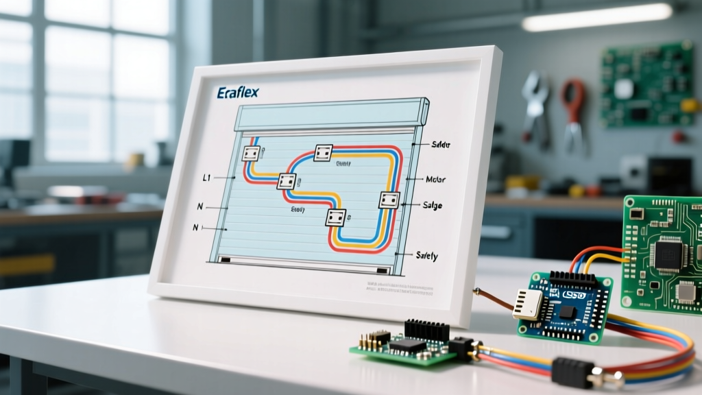
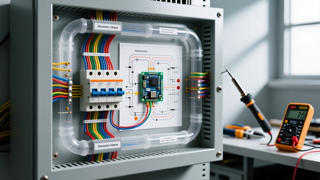
Whether you are upgrading a stock 48V commuter scooter to a 72V high-performance beast or building a custom electric mobility platform from scratch, the motor controller is the undisputed brain of your vehicle. A precise electric scooter controller wiring diagram is not just a suggestion; it is a critical safety document. Incorrect wiring can lead to catastrophic MOSFET blowouts, lithium battery fires, or permanent motor demagnetization.
In modern 2026 electric vehicle (EV) builds, the shift toward Field Oriented Control (FOC) via platforms like the VESC Project has made wiring more complex but infinitely more efficient. FOC requires pristine signal integrity, meaning your hall sensor wiring and phase wire routing must be executed with surgical precision. This guide provides a deep-dive reference into the standard pinouts, wire gauge requirements, and real-world failure modes associated with generic and premium brushless DC (BLDC) scooter controllers.
Core Power Architecture: Battery and Main Lines
The thickest wires on your controller harness handle the raw DC current from your battery pack. For high-performance scooters drawing 40A to 100A+ continuous current, voltage drop and heat generation are your primary enemies.
Main Battery Positive (B+) and Negative (B-)
- Wire Gauge: 8 AWG silicone-stranded copper for systems up to 60A continuous. For 80A+ continuous draws (common in dual-motor 72V setups), step up to 6 AWG or even 4 AWG.
- Connector Standard: XT90-S (Anti-Spark) is the industry standard. The anti-spark resistor loop prevents the violent inrush current that damages battery BMS MOSFETs and causes connector pitting.
- Pre-Charge Circuit: If your controller lacks an integrated pre-charge resistor, you must wire an external pre-charge switch or use an anti-spark connector to protect the controller's main capacitors.
Expert Insight: Never use PVC-insulated wire for main battery lines. The high-frequency switching of the controller can cause PVC insulation to melt and short against the scooter's deck. Always use 600V-rated high-strand-count silicone wire.
Motor Phase Wires: The High-Current Output
The controller converts DC battery power into 3-phase AC power to drive the BLDC hub motor. These are typically the three thickest wires exiting the controller, colored Yellow, Green, and Blue.
Phase Wire Routing and Crimping
Phase wires carry the same high current as the main battery lines but are subjected to intense electromagnetic interference (EMI). According to guidelines adapted from the NFPA National Electrical Code regarding high-frequency power transmission, keeping AC phase wires separated from low-voltage DC signal wires is mandatory to prevent signal cross-talk.
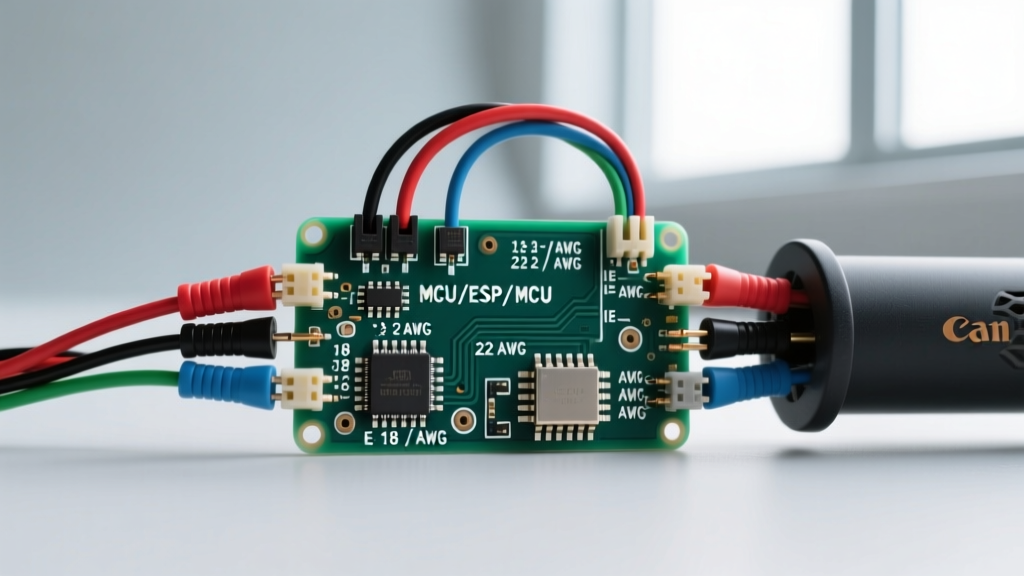
- Wire Gauge: 12 AWG to 10 AWG silicone wire.
- Connectors: MR30 (4mm bullet) or 5.5mm gold-plated bullet connectors. Avoid XT60 for phase wires; the flat contact surface cannot handle the sustained 3-phase AC amperage without overheating.
- Failure Mode: A loose phase wire connection creates high resistance, generating massive heat that melts the connector and instantly blows the corresponding MOSFET bank inside the controller.
Hall Sensor Wiring: The Rotor Position Feedback
Hall effect sensors are embedded in the motor stator to tell the controller the exact position of the rotor magnets. Without accurate hall signals, the controller cannot commutate the phases correctly, resulting in a stuttering motor or a complete failure to start.
The 5-Pin JST-SM Harness
The standard hall sensor connector is a 5-pin JST-SM plug. The pinout is almost universally standardized across Asian and Western controller manufacturers:
- Red: +5V DC (Power supply from the controller's internal voltage regulator)
- Black: Ground (GND)
- Yellow: Hall Signal A (Phase A)
- Green: Hall Signal B (Phase B)
- Blue: Hall Signal C (Phase C)
Note: Always verify the 5V and GND pins with a multimeter before plugging in the motor. Reversing these two wires will instantly fry the motor's internal hall sensors, requiring a difficult stator teardown to replace.
Comprehensive Controller Pinout & Wire Gauge Matrix
The following table serves as a quick-reference matrix for standard 48V-72V electric scooter controllers (including Sabvoton, VESC 6.6, and Kelly KLS variants).
| Function | Wire Color (Standard) | Recommended Gauge | Connector Type | Voltage / Signal Type |
|---|---|---|---|---|
| Battery Positive (B+) | Red | 8 AWG - 6 AWG | XT90-S / QS8 | 48V - 84V DC |
| Battery Negative (B-) | Black | 8 AWG - 6 AWG | XT90-S / QS8 | Ground Reference |
| Motor Phase A | Yellow | 12 AWG - 10 AWG | MR30 / 5.5mm Bullet | 3-Phase AC (PWM) |
| Motor Phase B | Green | 12 AWG - 10 AWG | MR30 / 5.5mm Bullet | 3-Phase AC (PWM) |
| Motor Phase C | Blue | 12 AWG - 10 AWG | MR30 / 5.5mm Bullet | 3-Phase AC (PWM) |
| Throttle Signal | White / Green | 22 AWG | JST-SM (3-pin) | 0.8V - 4.2V Analog |
| E-Brake Cutoff | White / Black | 22 AWG | JST-SM (2-pin) | Active Low (GND trigger) |
| CAN Bus High (BMS) | Yellow (Twisted Pair) | 24 AWG Shielded | JST-SM (4-pin) | CAN H (Differential) |
Auxiliary Systems: Throttle, Brakes, and BMS Communication
Throttle and Brake Cutoffs
The throttle is a simple Hall-effect linear sensor. It requires a 5V supply, a ground, and outputs a variable voltage signal (typically 0.8V at rest, rising to 4.2V at full twist). Safety Critical: Your wiring diagram must include electronic brake (e-brake) cutoffs. These are usually "Active Low" circuits. When you pull the brake lever, the signal wire is pulled to Ground, telling the controller to immediately cease PWM output. Wiring brakes as "Active High" is dangerous, as a severed brake wire would disable the safety cutoff.
CAN Bus and RS485 BMS Integration
Modern high-capacity scooter builds utilize smart Battery Management Systems (BMS). As detailed by Battery University, monitoring individual cell group voltages and temperatures in real-time prevents thermal runaway. Controllers equipped with CAN Bus or RS485 ports allow the BMS to throttle back the controller's current limit dynamically if a cell group sags below 3.0V or if the battery temperature exceeds 55°C. Always use shielded twisted-pair cable for CAN Bus wiring to prevent EMI from the phase wires from corrupting the data packets.
Real-World Troubleshooting & Failure Modes
Even with a perfect wiring diagram, physical execution errors cause 90% of controller failures. Here is how to diagnose the most common edge cases:
1. Motor Stutters and "Kicks" Under Load
- Root Cause: Hall sensor signal degradation due to EMI, or a 120-degree/60-degree phase angle mismatch.
- The Fix: Check the physical routing of the hall sensor cable. It must not be zip-tied parallel to the motor phase wires. If routing is correct, solder 0.1µF ceramic capacitors across the 5V and Signal pins at the controller end to filter out high-frequency PWM noise.
2. Controller Overheating at Low Speeds
- Root Cause: Running a square-wave controller at low speeds forces the MOSFETs to operate in their linear (high-resistance) region rather than fully saturated switching.
- The Fix: Upgrade to an FOC (Field Oriented Control) controller like a VESC or Kelly KLS. FOC uses sinusoidal waveforms, drastically reducing heat generation during low-speed, high-torque climbing scenarios.
3. Intermittent Power Loss Over Bumps
- Root Cause: Micro-fractures in solder joints or poor crimps on the main XT90 connector.
- The Fix: Never rely on solder alone for high-vibration connections. Use a proper ratcheting crimper (like the IWISS SN-28B for signal wires and a heavy-duty hex crimper for 8 AWG battery wires) and seal the connections with dual-wall adhesive-lined heat shrink to prevent moisture ingress and oxidation.
Final Safety Checklist Before Power-Up
Before connecting the main battery pack, perform this mandatory multimeter checklist:
- Verify continuity between the controller B- and the motor casing (should be OPEN/OL. If there is continuity, you have a phase-to-ground short).
- Verify the 5V and GND pins on the hall sensor plug match the motor's hall sensor pinout exactly.
- Ensure the throttle reads exactly 0.8V (or the manufacturer's specified deadzone) when at rest to prevent "runaway" acceleration upon power-up.
- Check that all phase wire bullet connectors are fully seated and covered with heat shrink to prevent debris-induced short circuits.
By treating your electric scooter controller wiring diagram as an engineering blueprint rather than a rough suggestion, you ensure a reliable, high-performance, and safe ride for years to come.