
The Critical Role of Code Compliance in Contactor Wiring
A contactor is the heavy-duty workhorse of industrial and commercial electrical systems, designed to safely switch high-current power circuits—most commonly for electric motors, HVAC compressors, and industrial heaters. However, simply connecting wires to the terminals is not enough. As of the 2026 enforcement cycles of the National Electrical Code (NEC / NFPA 70), inspectors are heavily scrutinizing motor control circuits for proper disconnecting means, overload protection, and precise torque terminations.
Creating a safe, code-compliant wiring diagram for a contactor requires a deep understanding of both the power circuit and the control circuit. A failure in either can result in catastrophic arc flashes, motor burnouts, or fatal electric shocks. This guide provides a professional, NEC-compliant framework for wiring a 3-pole magnetic contactor, integrating real-world specifications, torque requirements, and safety protocols mandated by OSHA and the NFPA.
Anatomy of a 3-Pole Contactor: Terminals and Functions
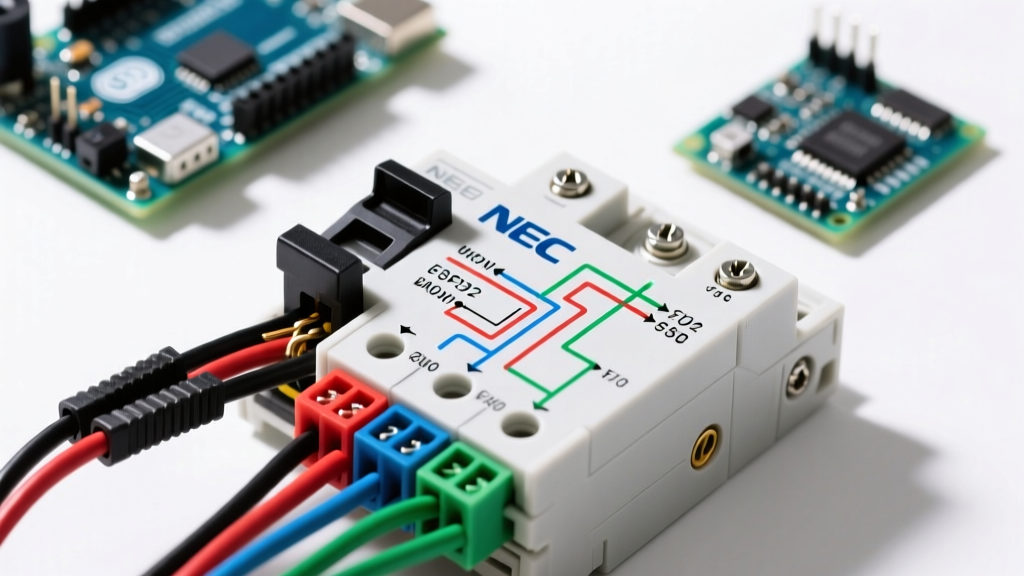
Before drafting your schematic, you must understand the physical layout of modern IEC and NEMA contactors. For this guide, we will reference the industry-standard Schneider Electric TeSys D (LC1D18) and the Eaton XTCE018B01, both rated for 18 Amps (approx. 5 HP at 230V 3-phase). In 2026, these units typically retail between $45 and $85, depending on the coil voltage and auxiliary contact blocks.
Power Circuit vs. Control Circuit
- Main Power Contacts (L1/T1, L2/T2, L3/T3): These carry the high-current load. 'L' designates the line (source) side, and 'T' designates the load (motor) side. Reversing these does not stop the contactor from working, but it violates NEC conventions and creates a severe shock hazard during maintenance, as the exposed bottom terminals would remain energized when the contactor is open.
- Coil Terminals (A1/A2): The electromagnetic coil that pulls the contacts closed. Common voltages include 120V AC, 240V AC, and 24V DC. A1 is typically the common or hot connection, while A2 is the neutral or switched return.
- Auxiliary Contacts (NO/NC): Used in the control circuit for holding seals, interlocks, or PLC feedback. Normally Open (NO) contacts close when the coil is energized; Normally Closed (NC) contacts open.
NEC-Compliant Wiring Diagram for a Contactor (Step-by-Step)
To ensure your installation passes inspection and operates safely, follow this sequence based on NFPA 70 (NEC) Article 430, which governs motors, motor circuits, and controllers.
Step 1: Sizing and Disconnecting Means (NEC 430.102)
The NEC strictly requires a disconnecting means for both the motor controller and the motor itself. For a 5 HP, 230V 3-phase motor (Full Load Current ~15.2A), you cannot rely solely on the contactor to isolate power. You must install a fused disconnect switch or a motor circuit protector (MCP) upstream of the contactor's L1, L2, and L3 terminals. The disconnect must be within sight of the controller and lockable in the OFF position to comply with OSHA lockout/tagout (LOTO) standards outlined in OSHA 1910.303.
Step 2: Overcurrent and Overload Protection (NEC 430.32 & 430.52)
A common and dangerous mistake is confusing overcurrent protection (short circuits) with overload protection (sustained over-current causing thermal damage). Your wiring diagram must include:
- Branch Circuit Short-Circuit Protection: Fuses or a circuit breaker upstream of the disconnect, sized at a maximum of 250% of the motor FLC for inverse-time breakers (NEC 430.52).
- Motor Overload Relay: Mounted directly below the contactor (e.g., Schneider LRD series or Eaton XTCEXF). The power wires from the contactor's T1, T2, and T3 terminals must route directly through the overload relay before heading to the motor. The relay's normally closed (NC) auxiliary contact (terminals 95/96) must be wired in series with the contactor's A1/A2 coil circuit to drop out the contactor if the motor overheats.
Step 3: Control Circuit Wiring and Coil Protection
The control circuit requires its own protection. If you are stepping down 480V to 120V for the coil using a control transformer, the secondary side must be protected by a supplemental fuse or miniature circuit breaker (MCB) rated no higher than the transformer's secondary current rating. Wire the start/stop pushbuttons and the overload relay's NC contact in series with the A1 terminal. Wire a NO auxiliary contact in parallel with the start button to create the standard 3-wire holding (seal-in) circuit.
Terminal Identification and Torque Specifications
Under NEC 110.14(D), all electrical connections must be tightened to the manufacturer's specified torque using a calibrated torque tool. Hand-tightening is a direct code violation and a leading cause of thermal runaway and fires.
| Terminal Type | Designation | Wire Gauge (18A Load) | Required Torque (M3.5 Screw) | Tool Requirement |
|---|---|---|---|---|
| Main Power (L/T) | L1-L3, T1-T3 | 12 AWG THHN Cu | 1.2 Nm to 1.7 Nm (10.6 - 15 lb-in) | Calibrated Torque Screwdriver |
| Coil Control | A1, A2 | 14 AWG THHN Cu | 1.2 Nm (10.6 lb-in) | Calibrated Torque Screwdriver |
| Auxiliary / Overload | NO/NC, 95/96 | 16 AWG THHN Cu | 0.8 Nm to 1.2 Nm (7 - 10.6 lb-in) | Precision Torque Driver |
Safety Warning: Never use standard wire ferrules on stranded wire without crimping them to the manufacturer's pull-out force specifications. A loose ferrule inside a contactor terminal can arc, melt the housing, and cause a phase-to-phase short circuit.
Common Failure Modes and Code Violations to Avoid
Even with a perfect wiring diagram for a contactor on paper, field execution often introduces critical flaws. Be vigilant against these specific failure modes:
1. Contact Welding from High Inrush Currents
Contactors are rated by utilization categories. An AC-3 rated contactor (like the TeSys D LC1D18) is designed for starting and stopping squirrel-cage motors. If you use this same contactor to switch a resistive heating bank or a high-inertia load requiring frequent jogging (AC-4 category), the massive inrush current can weld the silver-alloy contacts together. If contacts weld, the motor will not stop when the stop button is pressed, creating a lethal hazard.
2. Coil Burnout from Voltage Drop
Contactor coils require a minimum of 85% of their nominal voltage to pull in reliably. If your control circuit uses undersized wire (e.g., 18 AWG over a 150-foot run), the voltage drop at the A1/A2 terminals may fall below 100V on a 120V coil. The contactor will chatter, fail to fully close, and the coil will draw excessive current and burn out. Always calculate voltage drop for control circuits and upsize wire accordingly.
3. Missing Phase Loss Protection
If one phase of a 3-phase supply is lost while the motor is running, the motor will single-phase, drawing massive current on the remaining two legs. While a properly sized overload relay will eventually trip, a dedicated Phase Loss / Phase Reversal relay (e.g., Schneider RM22TG20) wired into the control circuit provides instantaneous protection, preventing catastrophic motor winding damage.
Frequently Asked Questions (FAQ)
Can I wire a 3-phase motor to a single-pole contactor?
No. NEC Article 430 requires all ungrounded conductors of a 3-phase motor to be simultaneously disconnected. You must use a 3-pole contactor. Using single-pole contactors for each phase is a severe code violation and creates an imbalance that will destroy the motor.
Do I need to wire the auxiliary contacts if I only want to turn the motor on and off?
While the main power contacts (L/T) and the coil (A1/A2) are the only strictly required connections for basic operation, omitting the auxiliary contacts means you cannot build a standard 3-wire seal-in circuit with standard momentary pushbuttons. You would have to use a maintained (toggle) switch, which is generally discouraged in industrial environments for safety reasons, as the motor will automatically restart when power is restored after an outage.
What is the difference between a contactor and a motor starter?
A contactor is simply the switching device (the electromagnetic relay). A motor starter is an assembly that includes the contactor plus the overload relay and often a fused disconnect. When drafting your wiring diagram, you are technically wiring a motor starter assembly, even if you are mounting the components individually on a DIN rail.