
Bridging Bathroom Wiring and Motor Circuit Fundamentals
When homeowners and electricians search for a bathroom electrical wiring diagram, they are usually looking at the circuit from the breaker panel to the wall switch. However, from a motor wiring tutorial perspective, the most critical connections happen inside the fan housing itself. A bathroom exhaust fan is fundamentally a motor load, and treating it as a simple resistive light fixture is a common mistake that leads to premature motor burnout, nuisance tripping, and excessive noise.
As of the 2026 construction season, the landscape of bathroom ventilation has shifted dramatically. Electronically Commuted Motors (ECMs) have largely replaced legacy shaded-pole motors in mid-to-high-end installations. This guide bridges standard residential wiring practices with advanced motor termination techniques, ensuring your installation is safe, code-compliant, and optimized for the specific motor topology you are installing.
The Evolution of Bathroom Fan Motors: Shaded-Pole vs. ECM
Before executing any bathroom electrical wiring diagram, you must identify the motor type inside the housing. The wiring methodology and power quality requirements differ significantly between the two dominant motor types on the market today.
1. Legacy Shaded-Pole Motors (AC Induction)
Found in budget-friendly units like the Broan-NuTone 505 (typically retailing around $25 to $35), shaded-pole motors are simple, rugged, and require only a basic hot, neutral, and ground connection. They have a high inrush current and operate at a fixed speed determined by the 60Hz line frequency. Because they lack internal electronics, they are highly tolerant of minor voltage drops and dirty power.
2. Electronically Commutated Motors (ECM / DC Brushless)
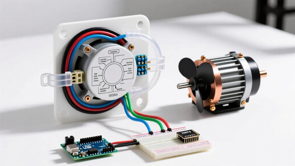
Premium units, such as the highly rated Panasonic WhisperCeiling FV-0511VQ1 (retailing between $140 and $160), utilize ECM technology. These motors feature an internal driver board that converts AC line voltage to DC, allowing for variable speed control, ultra-quiet operation, and high energy efficiency. Motor Wiring Insight: ECM driver boards are sensitive to voltage fluctuations. Using undersized wire or creating loose, high-resistance terminations at the housing can cause the internal logic board to fault, resulting in a fan that hums but refuses to spin.
Decoding the Standard Bathroom Electrical Wiring Diagram
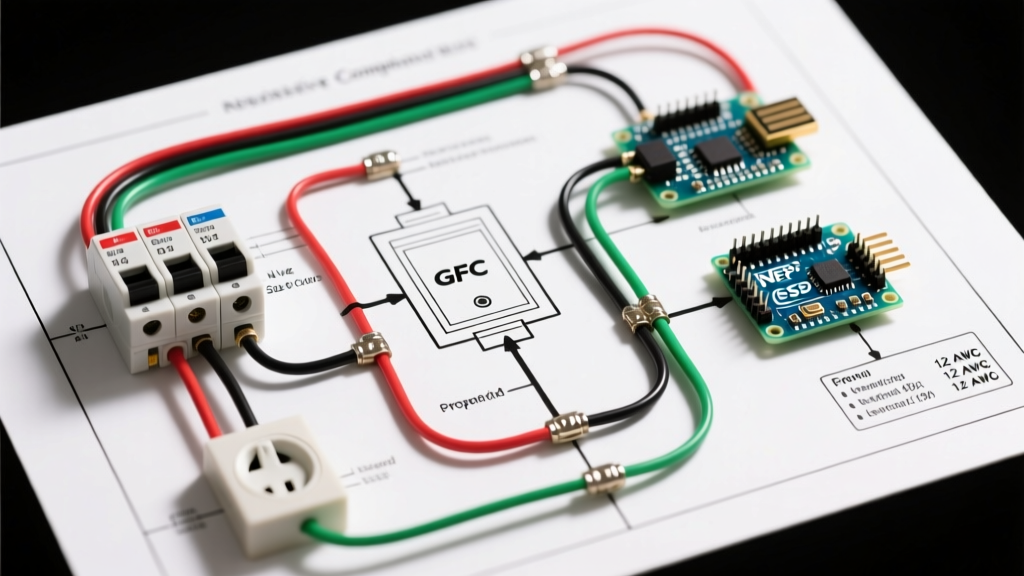
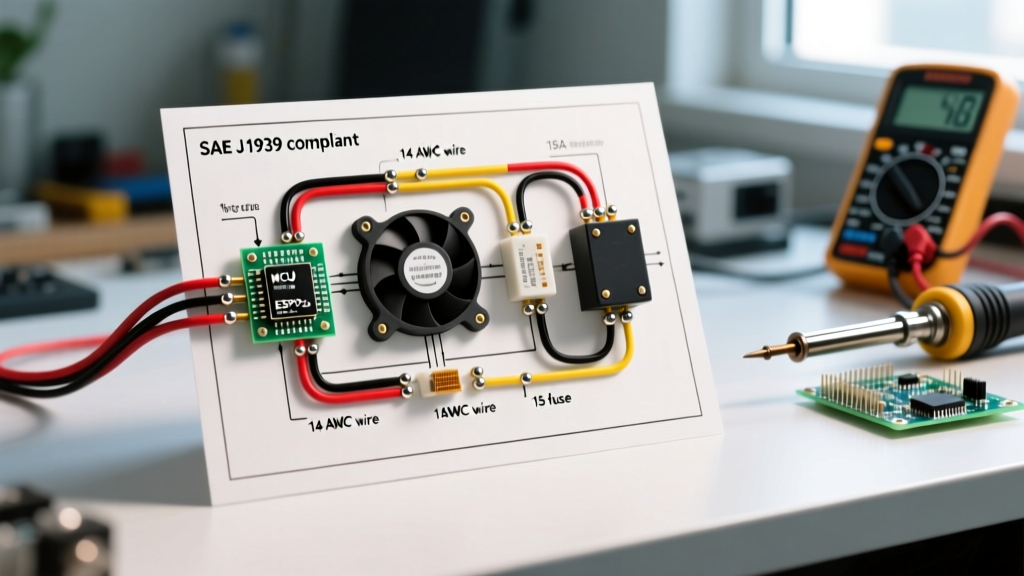
For a standard, single-function exhaust fan (no light, no heater), the wiring diagram is remarkably straightforward, but the execution requires precision. Below is the textual schematic mapping for a standard 15-Amp branch circuit.
- Power Source: 120V AC from a 15A or 20A breaker (AFCI protected per modern NEC).
- Cable to Switch: 14/2 NM-B (for 15A) or 12/2 NM-B (for 20A) carrying Line (Black), Neutral (White), and Ground (Bare).
- Switch Loop: The white wire in the 14/2 cable running from the switch to the fan must be re-identified (wrapped in black electrical tape) to serve as the Switched Hot.
- Motor Termination: Switched Hot connects to the motor's black lead; Line Neutral connects to the motor's white lead; Bare copper connects to the green ground screw on the motor housing.
Expert Tip: Never rely on the metallic flex conduit or the mounting brackets to serve as your equipment grounding conductor (EGC) for the motor housing. Always run a dedicated bare copper or green insulated ground wire directly to the green grounding screw inside the fan's junction box.
Step-by-Step Motor Termination Tutorial
The environment inside a bathroom ceiling cavity is subject to extreme thermal cycling and high humidity. Standard twist-on wire nuts often fail in these conditions over time, leading to arcing. Follow this motor-focused termination protocol:
- Prepare the NM-B Cable: Strip exactly 3/4 inch of insulation from the 14 AWG or 12 AWG solid copper conductors. Do not nick the copper, as scoring solid wire creates a weak point that can snap under thermal expansion.
- Prepare the Motor Leads: Fan motors typically use 18 AWG stranded wire. Strip 1/2 inch of insulation. Do not tin (solder) the stranded wire; solder creates a rigid joint that can crack under the micro-vibrations of the motor.
- Use Lever Connectors: Discard the included twist-on wire nuts. Use WAGO 221-412 lever nuts (approx. $0.60 each). These connectors perfectly bridge the gap between 18 AWG stranded motor leads and 14 AWG solid branch circuit wires, providing a gas-tight, vibration-proof connection.
- Secure the Ground: Form a pigtail using a green wire nut or a WAGO 221-413 to connect the branch circuit ground, the housing ground screw, and the motor ground lead together.
- Cable Clamping: Ensure the NM-B cable is secured to the fan's internal junction box using a proper 3/8-inch NM cable connector. The motor's vibration will eventually strip the wire insulation if the cable is allowed to move freely.
Wire Gauge, Breaker Sizing, and Motor Load Matrix
Selecting the correct wire and breaker is dictated by the National Electrical Code (NEC) and the specific amperage draw of the motor. While most single bathroom fans draw less than 1.0 Amp, the circuit must be sized for the entire bathroom load (including receptacles and lighting).
| Circuit Breaker | Wire Gauge (NM-B) | Max Continuous Load | Typical Application |
|---|---|---|---|
| 15 Amp (AFCI/GFCI) | 14 AWG (14/2 or 14/3) | 12 Amps (1440W) | Standard Fan + LED Lighting |
| 20 Amp (AFCI/GFCI) | 12 AWG (12/2 or 12/3) | 16 Amps (1920W) | Fan + Lighting + Receptacles |
| 20 Amp (Dedicated) | 12 AWG (12/2) | 16 Amps (1920W) | Multi-function Fan/Heater Units |
Multi-Function Units: Wiring Heater, Light, and Fan Motors
If your bathroom electrical wiring diagram includes a multi-function unit (like the Broan Sensonics series), you are no longer wiring a simple motor; you are managing three distinct loads. The heating element alone can draw 12.5 Amps (1500W).
For these units, you must run 12/3 NM-B cable (or two separate 12/2 cables) from a dedicated 20-Amp double-pole or tandem breaker setup to the wall switch box. The internal motor wiring remains the same, but the switch box will require a multi-pole rocker switch. Ensure the neutral wires for the motor and the heater are kept isolated on their respective load sides if the manufacturer's diagram dictates separate neutral returns, though most modern units share a single neutral bus inside the housing.
2026 NEC Code Compliance & Safety Requirements
Electrical codes evolve, and bathroom circuits are heavily scrutinized due to the presence of water. When installing or modifying a bathroom fan motor circuit, adhere to the latest NFPA 70 (National Electrical Code) guidelines:
- GFCI Protection: If the exhaust fan is located directly over a shower or bathtub, it must be GFCI protected and specifically listed for use over a wet location. Standard fans are only rated for damp locations (e.g., over a vanity).
- AFCI Protection: Under NEC Article 210.12, all 120V, single-phase, 15- and 20-amp branch circuits supplying outlets in dwelling unit bathrooms require Arc-Fault Circuit Interrupter (AFCI) protection. Use an AFCI breaker at the panel, or an AFCI/GFCI dual-function breaker if the circuit also feeds bathroom receptacles.
- Ventilation Standards: The EPA Energy Star program recommends continuous run fans or timer-equipped fans to meet modern ASHRAE 62.2 air exchange rates. If wiring a timer switch, ensure the timer requires a neutral wire; legacy mechanical timers do not, but modern digital countdown timers do, requiring a 14/3 cable to the switch box.
Troubleshooting Common Motor Wiring Failures
Even with a perfect bathroom electrical wiring diagram on paper, field conditions can cause motor issues. Here is how to diagnose them:
The Motor Hums but the Fan Blade Does Not Spin
Cause: In shaded-pole motors, this usually indicates a seized bearing or a failed start capacitor (if equipped). In ECM motors, this indicates a locked rotor error detected by the driver board, often caused by debris in the blower wheel or an undervoltage condition at the housing. Fix: Check voltage at the motor leads with a multimeter while the switch is ON. If you read 115V-120V and the motor won't spin, the motor assembly must be replaced. If you read less than 110V, trace the circuit back for a high-resistance connection or loose wire nut.
Nuisance GFCI Tripping When the Fan Turns Off
Cause: Inductive motor loads generate a voltage spike (back-EMF) when the circuit is opened. This spike can leak to ground through the motor's internal capacitance, tricking a highly sensitive GFCI breaker. Fix: Ensure the GFCI breaker is a modern, nuisance-trip-resistant model. If the problem persists, install an RC snubber (resistor-capacitor network) across the motor's hot and neutral leads to absorb the inductive kickback.
Final Thoughts on Bathroom Motor Wiring
A successful bathroom ventilation project relies on understanding that the fan is a dynamic motor load, not a static lightbulb. By selecting the correct wire gauge, utilizing vibration-proof lever connectors, and respecting the specific needs of ECM driver boards, you ensure a quiet, efficient, and code-compliant installation. For further reading on residential electrical safety, consult the Consumer Product Safety Commission's electrical safety guidelines before beginning any DIY wiring project.