
The Hidden Dangers of Unverified Schematics
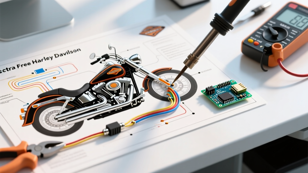
Touring motorcycles like the Harley-Davidson Electra Glide (FLHX and FLHTCU models) feature some of the most complex electrical architectures in the two-wheeled world. Following the 2014 Project Rushmore updates and the subsequent integration of the Boom! Box GTS infotainment systems in recent 2024–2026 models, the wiring harness has evolved from simple point-to-point 12V circuits into a highly sensitive Controller Area Network (CAN-bus). When riders search for electra glide free harley davidson wiring diagrams on enthusiast forums or third-party PDF repositories, they are often met with outdated, mislabeled, or heavily modified schematics. Relying on these unverified documents is not just a matter of convenience; it is a severe safety and code compliance hazard.
A mismatched diagram can easily lead a DIY mechanic to cross a 12V switched ignition wire with a CAN-High data line. Because the CAN-bus operates on low-voltage differential signaling (typically 2.5V to 3.5V), introducing 12V into this circuit will instantly destroy the Body Control Module (BCM) or the Engine Control Module (ECM)—components that cost upwards of $1,200 to replace and require dealer-level proprietary software to flash and pair.
OEM Service Manuals vs. Free Forum Diagrams
To understand the risk profile, we must compare the data integrity of official documentation against crowdsourced alternatives. The table below highlights the critical differences you face when working on a 2018–2026 Electra Glide Standard or Ultra Limited.
| Feature | OEM TechLink Service Manual | Free Forum / Third-Party Diagrams |
|---|---|---|
| Model Year Accuracy | Exact pinouts for the specific VIN and model year. | Often mislabeled; a 2012 schematic might be posted in a 2019 thread. |
| CAN-Bus Routing | Details 120-ohm termination resistor locations and shielded twisted pairs. | Omits data lines or shows them as standard 12V accessory wires. |
| Wire Gauge & Color | Specifies exact AWG and factory color codes (e.g., W/Y for White/Yellow). | Faded scans make distinguishing Red/Orange from Solid Red impossible. |
| Connector Pin Views | Provides mating-side vs. wire-side pinout matrices for Metri-Pack and Deutsch connectors. | Rarely includes pin-side orientation, leading to reversed polarity insertions. |
| Cost | ~$120/year for a DIY TechLink subscription (2026 pricing). | $0 (but carries a high risk of catastrophic component failure). |
SAE Compliance and Thermal Management Under the Seat
Motorcycle wiring is not governed by the National Electrical Code (NEC) used in residential buildings, but it is strictly regulated by the Society of Automotive Engineers (SAE) and the Department of Transportation (DOT). According to the SAE International Standards database, primary automotive wire must meet SAE J1128 specifications for low-tension cables. This standard dictates strict thermal and abrasion resistance requirements.
The Exhaust Proximity Hazard
On the Electra Glide, the main wiring harness and battery routing pass dangerously close to the rear exhaust header and the oil cooler lines. Ambient temperatures in these zones routinely exceed 100°C (212°F) during summer touring. Standard PVC-insulated wire (rated for 80°C–105°C) will become brittle, crack, and eventually short out against the frame. If a free diagram instructs you to run standard 14AWG PVC wire for an auxiliary accessory near the right-side saddlebag rail, you are creating a fire hazard. Code-compliant DIY repairs require Cross-Linked Polyethylene (XLPE) or Tefzel-insulated wire, which can withstand continuous temperatures up to 150°C (302°F).
FMVSS 108: Lighting and Auxiliary Lamp Compliance
A common modification shown in free Electra Glide diagrams is the installation of auxiliary passing lamps or LED saddlebag accent lighting. However, modifying the lighting circuit directly impacts compliance with Federal Motor Vehicle Safety Standard 108 (FMVSS 108), which governs lamps, reflective devices, and associated equipment. The Federal Motor Vehicle Safety Standards (FMVSS) mandate specific photometric outputs, beam patterns, and color restrictions.
Compliance Warning: Splicing high-draw aftermarket LED halos directly into the OEM running light circuit (often Pin 2 on the headlamp nacelle connector) without a dedicated relay and inline fuse can overload the BCM's internal solid-state switching transistor. This will trigger a 'LAMP OUT' fault on the dash and may permanently disable the running light circuit until the BCM is reset or replaced.
Always use an isolated relay harness triggered by the OEM wire, rather than feeding the load directly through the factory switchgear. Ensure all forward-facing auxiliary lamps emit only white or amber light, as red or blue forward-facing illumination violates DOT regulations and will result in immediate citations.
Step-by-Step Verification Protocol for Free Diagrams
If you must use a free diagram found online because you lack access to the OEM TechLink portal, you must independently verify every circuit before cutting, stripping, or crimping a single wire. Follow this rigorous validation protocol using a True-RMS digital multimeter, as recommended by Fluke's guide on multimeter best practices.
- Isolate the Battery: Always disconnect the negative (ground) terminal first, followed by the positive. Wait 5 minutes for the CAN-bus modules to enter 'sleep' mode and discharge capacitors.
- Verify Ground Integrity: Set your multimeter to continuity mode. Probe the suspected ground wire on the harness and a known clean, unpainted metal point on the engine block. A reading below 0.5 ohms confirms a valid chassis ground.
- Test for Switched vs. Constant 12V: Reconnect the battery temporarily. With the ignition OFF, probe the wire. If it reads 12.6V, it is a constant battery feed (e.g., for the clock or BCM memory). Turn the ignition to ACC/ON. If the wire only shows 12.6V in this position, it is a switched feed. Free diagrams frequently swap these two, which will result in a parasitic battery drain overnight.
- Check for CAN-Bus Presence: Switch the multimeter to DC Voltage. Probe the suspected data lines. CAN-High should read approximately 2.5V to 3.5V, and CAN-Low should read 1.5V to 2.5V relative to ground. If you read a solid 12V, you have misidentified the circuit; do not splice your accessory into this line.
- Perform a Voltage Drop Test: Under load, measure the voltage drop across the length of the wire and its connectors. A drop greater than 0.1V per connection indicates high resistance, corrosion, or an undersized wire gauge that violates SAE current-carrying capacity guidelines.
Proper Termination: Abandoning the Butt-Splice
The most glaring safety violation in free DIY wiring guides is the recommendation to use solder-less crimp butt-splices wrapped in electrical tape. Electrical tape degrades under heat and UV exposure, eventually unraveling and exposing live copper to the elements. Furthermore, standard crimpers often deform the barrel, creating a high-resistance joint that generates localized heat.
For a safe, code-compliant repair on an Electra Glide, you must use environmental-sealed connectors. The industry standards are:
- Deutsch DT Series: Ideal for high-current applications (up to 13A per contact) such as heated grips, auxiliary lights, and cooling fan relays. Requires specific silicone sealing plugs and a ratcheting crimper.
- AMP Superseal 1.5 / Metri-Pack 280: Used for low-current sensor and CAN-bus splices. These feature integrated secondary locking tabs to prevent vibration-induced disconnects, a common failure mode on V-Twin engines.
- Adhesive-Lined Heat Shrink: If splicing is absolutely unavoidable, use 3:1 shrink ratio polyolefin tubing with an internal layer of hot-melt adhesive. When heated, the adhesive flows into the wire strands, creating a waterproof, strain-relieved seal that outlasts the motorcycle.
Final Thoughts on Electrical Safety
While the temptation to save money by utilizing an electra glide free harley davidson wiring diagrams PDF is understandable, the financial and physical risks far outweigh the initial savings. An electrical fire on a touring motorcycle, miles from home, is a catastrophic event. Invest in the proper diagnostic tools, adhere strictly to SAE and FMVSS standards, and when in doubt, purchase the official service documentation to ensure your ride remains safe, reliable, and street-legal.