
Strategic Electrical Planning for Commercial Zero-Turn Mowers
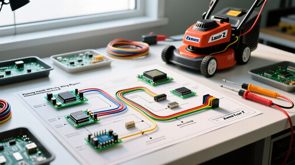
Upfitting a commercial zero-turn mower requires more than just splicing wires and taping connections. For landscaping fleets and independent operators in 2026, the electrical system of an Exmark Lazer Z is the central nervous system that powers not only the engine and PTO clutch but also modern telematics, LED work lights, and electric sprayers. Relying on guesswork when adding accessories leads to voltage drops, melted harnesses, and voided warranties. By thoroughly studying the wiring diagram for Exmark Lazer Z models before cutting a single zip-tie, you can ensure your installation is safe, reliable, and optimized for the machine's specific stator output.
This installation planning guide breaks down the factory electrical architecture, decodes standard Exmark wire color codes, and provides actionable frameworks for calculating amperage budgets and selecting the correct wire gauges for your aftermarket accessories.
Core Electrical Architecture of the Lazer Z Platform
Before modifying the harness, you must understand the baseline power generation. Most modern Exmark Lazer Z X-Series and S-Series models (such as the LZS801GKA604A1) are powered by Kohler Command PRO or Kawasaki FX engines. These engines utilize a single-phase or dual-phase stator paired with a voltage regulator/rectifier to convert AC voltage to 12V DC.
CRITICAL STATOR LIMITATION: The average Kohler stator on a Lazer Z produces a peak output of 15 to 20 amps at 3,600 RPM (full throttle). However, at idle or low-RPM transit speeds, output drops to 8-10 amps. If your aftermarket accessories draw more than the stator's low-RPM output, the system will pull the deficit from the U1 battery (typically 300-350 CCA), leading to premature battery sulfation and failure.Decoding Factory Wire Color Standards
While you should always verify against the specific schematic for your serial number, Exmark generally adheres to the following color codes in their main harnesses. Understanding these is crucial when tapping into the ignition switch or safety interlock modules.
- Red (Heavy Gauge): Unswitched 12V+ directly from the battery/starter solenoid.
- Black: Main chassis ground.
- Purple: PTO (Power Take-Off) clutch engagement circuit.
- Orange / Yellow: AC output from the stator (pre-rectifier). Never tap into these wires for DC accessories.
- White: Switched 12V+ (active only when the ignition key is in the 'Run' position).
- Green: Safety interlock module outputs (seat switch, lap bar neutral sensors).
Step 1: Calculate Your Amperage Budget
The most common installation failure on commercial mowers is stator burnout caused by overloading the 12V system. Before purchasing an LED light bar or an electric spray pump, map out your total amperage draw and compare it against the factory baseline.
| Component / Accessory | Typical Amperage Draw | Installation Notes |
|---|---|---|
| Factory Ignition & ECU | 2.5 - 4.0 Amps | Baseline draw. Do not modify. |
| PTO Clutch (e.g., Ogura/Warner) | 3.5 - 4.5 Amps | Heavy inductive load. Requires flyback diode. |
| OEM LED Light Kit (Exmark #117-9491) | 2.2 Amps | Plugs into factory switched harness. |
| Aftermarket 40W LED Light Bar | 3.3 Amps | Requires dedicated relay; do not use OEM plug. |
| GPS / Telematics Tracker (e.g., Samsara) | 0.5 - 1.0 Amps | Must be wired to constant 12V for sleep-mode pinging. |
| 12V Electric Sprayer Pump (e.g., ShurFlo) | 8.0 - 12.0 Amps | High draw. Requires 30A relay directly to battery. |
For detailed engine-specific stator outputs, always cross-reference the Kohler Engines Technical Service Manuals corresponding to your exact engine family and spec number.
Step 2: Wire Gauge Selection and Routing
Using the wrong wire gauge in a high-vibration, high-heat environment like a mower engine bay is a fire hazard. According to SAE Standard J1128 for low-tension primary automotive cable, wire sizing must account for both the amperage draw and the total length of the wire run (positive and negative combined). Voltage drop over long runs to the rear of a 72-inch deck Lazer Z can severely dim lights or cause sprayer pumps to stall.
Wire Sizing Matrix for 12V DC Mower Accessories
| Max Current | 0-10 ft Run | 10-20 ft Run | 20-30 ft Run |
|---|---|---|---|
| 5 Amps | 16 AWG | 14 AWG | 12 AWG |
| 10 Amps | 14 AWG | 12 AWG | 10 AWG |
| 15 Amps | 12 AWG | 10 AWG | 8 AWG |
| 20+ Amps | 10 AWG | 8 AWG | 6 AWG |
Pro-Tip for Routing: Never route 12V accessory wires near the exhaust manifold or the PTO clutch assembly. The PTO clutch generates intense electromagnetic interference (EMI) when disengaging, which can induce voltage spikes in nearby unshielded wires, potentially frying sensitive GPS telematics modules.
Common Installation Failure Modes & Edge Cases
Even with a perfect wiring diagram for Exmark Lazer Z mowers, field installations often fail due to environmental factors. Watch out for these specific edge cases:
- PTO Diode Burnout: The PTO clutch is a massive inductor. When the magnetic field collapses upon shutoff, it sends a high-voltage spike backward through the harness. Exmark installs a flyback diode in the PTO circuit. If you splice an aftermarket switch or relay into the purple PTO wire without preserving or upgrading this diode, the voltage spike will weld your relay contacts shut or destroy the ignition switch.
- Voltage Regulator Overheating: Adding high-draw LED lights without upgrading the stator forces the voltage regulator to work at 100% duty cycle to maintain 14.2V. In the summer months, ambient engine bay temperatures on a Lazer Z can exceed 180°F (82°C). This combination frequently causes the regulator's internal epoxy to crack, leading to a dead short. Always mount aftermarket regulators in high-airflow zones away from the muffler.
- Chassis Ground Corrosion: Commercial mowers are frequently pressure-washed. Using the mower frame as a ground return (single-wire routing) is a critical mistake. Exmark's powder-coated frames and the vibration of the mower loosen ground bolts, creating high-resistance connections. Always run a dedicated negative ground wire back to the battery's negative terminal or the main engine block ground stud.
Sourcing Official Schematics and Support
Never rely on generic 'zero-turn' wiring diagrams. The safety interlock modules and dash harness pinouts change significantly between a 2019 Lazer Z and a 2025 Lazer Z X-Series. To obtain the exact, serial-specific wiring diagram for your machine, use the official Exmark Support and Parts Lookup portal. Enter your model and serial number to download the precise Operator's Manual and Service Manual, which contain the fold-out electrical schematics required for professional-grade upfitting.
Final Checklist Before Powering Up: Verify all inline fuses are rated 20% higher than the accessory's max draw but lower than the wire's ampacity rating. Ensure all connections are sealed with marine-grade adhesive-lined heat shrink (not electrical tape), and confirm that all relays are mounted vertically to prevent moisture pooling inside the casing.