
Understanding the Well Pressure Switch and Motor Circuit
Wiring a submersible well pump requires a precise understanding of motor control circuits, voltage drop, and hydraulic pressure management. At the heart of this system is the pressure switch, a mechanical transducer that monitors the water system's pressure and actuates the pump motor accordingly. When searching for a reliable wiring diagram for well pressure switch configurations, it is critical to distinguish between direct-to-motor wiring (2-wire systems) and control-box-mediated wiring (3-wire systems). In this comprehensive motor wiring tutorial, we will break down the exact terminal mappings, wire gauge requirements, and failure modes for the industry-standard Square D Pumptrol 9013FSG2 pressure switch paired with a 230V single-phase submersible pump motor.
Safety Warning: Well pump circuits operate at 230V (or higher for 3-phase commercial setups) and involve water. Always shut off the main breaker and verify zero voltage with a CAT III multimeter before opening the pressure switch enclosure or control box. Ensure the well casing and all metallic plumbing are properly bonded to the main service ground per NEC Article 250.
Essential Components for a Standard 230V Submersible Setup
Before mapping the wiring diagram, verify you have the correct components. A standard residential 1.5 HP to 2 HP setup in 2026 typically utilizes the following hardware:
- Pressure Switch: Square D Pumptrol 9013FSG2 (Factory set to 40/60 PSI). Retail price ranges from $28 to $35. It features a NEMA 1 enclosure and silver-alloy contacts rated for 2 HP at 230V.
- Control Box (For 3-Wire Pumps): Franklin Electric 2823028100 (1.5 HP, 230V, 3-Wire). Contains the start capacitor, run capacitor, and heavy-duty relay. Priced around $160 to $190.
- Pressure Tank: Amtrol WX-202 (20-gallon equivalent) or larger. Must be pre-charged to 2 PSI below the switch's cut-in pressure (e.g., 38 PSI for a 40/60 switch).
- Circuit Breaker: 20-Amp or 30-Amp double-pole breaker, depending on the pump's Full Load Amps (FLA).
2-Wire vs. 3-Wire Submersible Pumps: Which Diagram Applies?
The wiring diagram for your well pressure switch depends entirely on the type of pump motor installed in the well bore.
The 2-Wire System (Direct Wiring)
In a 2-wire system, the start relay and capacitors are sealed inside the submersible motor housing. The pressure switch acts as the sole controller. Line voltage enters the switch, and the load side wires run directly down the well casing to the pump. This is simpler to wire but makes troubleshooting difficult; if the start capacitor fails, you must pull the entire pump from the well to replace it.
The 3-Wire System (Control Box Wiring)
In a 3-wire system, the start components are located in an above-ground control box. The pressure switch sends power to the control box, which then manages the motor's start and run windings. This is the preferred setup for motors 1 HP and larger, as it allows for easy replacement of capacitors and relays without pulling the pump.
Step-by-Step Wiring Diagram for Well Pressure Switch (230V 3-Wire)
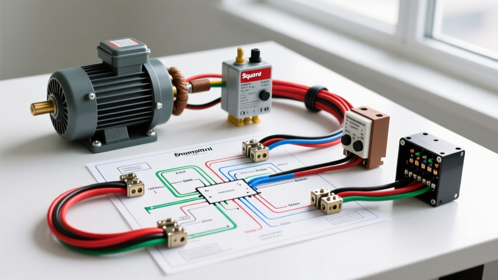
Below is the exact terminal mapping for wiring a Square D Pumptrol 9013FSG2 to a 230V single-phase 3-wire control box. The switch features four main terminal screws, typically labeled 1, 2, 3, and 4, along with a green grounding screw.
Step 1: Line Side Connections (Power In)
Run your 230V feeder cable from the double-pole breaker in your main panel to the pressure switch. Strip the insulation back 3/4 inch.
- Connect the Black (Line 1) wire to Terminal 1 on the pressure switch.
- Connect the Red or White (Line 2) wire to Terminal 2 on the pressure switch.
- Connect the Bare Copper (Ground) wire to the green grounding lug on the metal enclosure of the switch.
Step 2: Load Side Connections (To Control Box)
Run a second 230V cable from the pressure switch to the above-ground control box (or directly to the well head if using a 2-wire pump).
- Connect the Black (Load 1) wire to Terminal 3 on the pressure switch. Connect the other end to the L1 (Line 1) terminal inside the control box.
- Connect the Red/White (Load 2) wire to Terminal 4 on the pressure switch. Connect the other end to the L2 (Line 2) terminal inside the control box.
- Connect the Bare Copper (Ground) to the control box ground bar, ensuring continuity back to the main panel.
Step 3: Control Box to Pump Motor (Downhole Wiring)
The control box will have three output terminals for the downhole drop cable (usually colored Black, Red, and Yellow, plus a Green ground).
- Black (Run Winding): Connects to the control box 'B' terminal and the pump's black wire.
- Red (Start Winding): Connects to the control box 'R' terminal and the pump's red wire.
- Yellow (Common): Connects to the control box 'Y' terminal and the pump's yellow wire.
- Green (Ground): Spliced directly to the pump's green ground wire and bonded to the well casing.
Wire Gauge and Breaker Sizing Matrix
Undersized wiring causes severe voltage drop, leading to burnt contacts inside the pressure switch and premature motor failure. According to NFPA 70 (National Electrical Code), you must size the wire based on 125% of the motor's Full Load Amps (FLA), while also calculating voltage drop for the total distance from the panel to the pump motor (including the downhole drop cable).
| Motor HP | Voltage | Approx. FLA | Min. Wire Gauge (Short Run) | Breaker Size (Double Pole) |
|---|---|---|---|---|
| 1/2 HP | 230V | 3.2A | 14 AWG Copper | 15 Amp |
| 3/4 HP | 230V | 4.8A | 14 AWG Copper | 15 Amp |
| 1 HP | 230V | 6.6A | 12 AWG Copper | 20 Amp |
| 1.5 HP | 230V | 9.2A | 12 AWG Copper | 20 Amp |
| 2 HP | 230V | 11.6A | 10 AWG Copper | 30 Amp |
| 3 HP | 230V | 16.4A | 8 AWG Copper | 40 Amp |
Note: If the total wire run (feeder + drop cable) exceeds 250 feet, you must increase the wire gauge by one or two sizes to maintain voltage drop below 5% under running conditions, and below 15% during motor startup (Locked Rotor Amps).
Troubleshooting Common Wiring and Switch Failures
Even with a perfect wiring diagram for your well pressure switch, environmental and mechanical factors can cause system failures. Here is how to diagnose the most common issues:
1. Pitted or Burnt Contacts
Symptom: The pump hums but won't start, or the switch smells like ozone/burnt plastic. Cause: Opening a 230V inductive motor load creates an electrical arc. Over thousands of cycles, this arc pits the silver-alloy contacts, increasing resistance and causing voltage drop. Fix: Replace the pressure switch. Do not attempt to sand the contacts, as this removes the protective silver plating and accelerates future degradation. Ensure your breaker is correctly sized to handle the LRA (Locked Rotor Amps) without nuisance tripping.
2. Rapid Cycling (Short Cycling)
Symptom: The pressure switch clicks on and off every 10 to 20 seconds when a faucet is opened. Cause: This is rarely a wiring issue. It is almost always caused by a waterlogged pressure tank (bladder failure) or an incorrect air pre-charge. When the tank loses its air cushion, water is incompressible, causing pressure to spike instantly, shutting off the switch. Fix: Drain the tank completely. Use a tire gauge to check the Schrader valve. Inflate to exactly 2 PSI below the switch's cut-in pressure (e.g., 28 PSI for a 30/50 switch). If water sprays from the Schrader valve, the bladder is ruptured, and the tank must be replaced.
3. Switch Will Not Close (Pump Won't Turn On)
Symptom: Pressure is at 0 PSI, but the switch remains open. Cause: A clogged pressure port. The 1/4-inch pipe nipple connecting the switch to the water line is often filled with sediment, iron bacteria, or calcium scale, preventing water pressure from reaching the switch's internal diaphragm. Fix: Remove the switch, clear the port with a piece of stiff wire, and install a new brass or stainless steel nipple. Avoid using galvanized steel, which rusts and restricts flow.
Code Compliance and Best Practices
Adhering to electrical and environmental codes ensures the longevity of your well system. The Environmental Protection Agency (EPA) recommends annual testing of private well water, which indirectly affects your electrical system; highly mineralized or corrosive water can degrade downhole wire insulation and cause ground faults that trip your main breaker.
From an electrical standpoint, always install a dedicated disconnect switch within sight of the pressure switch and control box if the main panel is located far away. Furthermore, utilize waterproof, gel-filled wire splice kits (such as the King Innovation 21001) for all downhole drop cable connections. Standard electrical tape will degrade in the humid environment of a well casing, leading to ground faults and motor burnout. By following this wiring diagram for well pressure switch setups and respecting NEC grounding requirements, you will build a robust, safe, and long-lasting water delivery system.