
Decoding the Manufactured Home Electrical Architecture
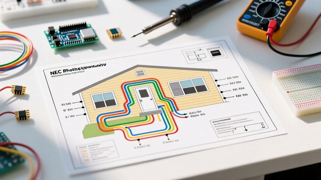
Unlike traditional site-built homes, manufactured homes (commonly referred to as mobile homes) feature a highly specialized electrical architecture governed by strict federal and national codes. When you are troubleshooting a faulty HVAC system, upgrading an electric range, or installing a new water heater, interpreting the mobile home electrical wiring diagram is the critical first step. These diagrams dictate how power flows from the exterior weatherhead or pedestal, through the main disconnect, into the crossover junction box, and finally to the interior distribution panel and appliance branch circuits.
Manufactured home wiring is regulated under HUD's Manufactured Home Construction and Safety Standards and the National Electrical Code (NEC) Article 550. A standard site-built home diagram assumes a fixed foundation and continuous grounding electrode system, whereas a mobile home diagram must account for chassis grounding, flexible crossover connections, and specialized panelboard placements. Misinterpreting these diagrams can lead to severe safety hazards, including neutral-to-ground bonding faults and overloaded feeder lines.
Safety Warning: Before tracing any circuit on a mobile home electrical wiring diagram, ensure the main exterior disconnect is locked out and tagged out (LOTO). Mobile homes often have a main breaker located on the exterior pedestal or a wall-mounted disconnect near the entry door, separate from the interior branch circuit panel.
Appliance Circuit Specifications Matrix
When reading the wiring diagram for a manufactured home, you will notice that major 240V appliances require dedicated double-pole breakers and specific cable types. The diagram will typically specify whether the installer used Copper or Aluminum branch wiring. Below is the standard 2026 specification matrix for major appliance circuits in modern manufactured homes.
| Appliance | Voltage | Amperage | Wire Gauge (Copper) | Breaker Type | Receptacle / Connection |
|---|---|---|---|---|---|
| Electric Range | 240V | 50A | 6/3 AWG w/ Ground | 2-Pole 50A | NEMA 14-50R |
| Electric Dryer | 240V | 30A | 10/3 AWG w/ Ground | 2-Pole 30A | NEMA 14-30R |
| Water Heater | 240V | 30A | 10/2 AWG w/ Ground | 2-Pole 30A | Hardwired / Junction Box |
| Central HVAC Condenser | 240V | 40A | 8/2 AWG w/ Ground | 2-Pole 40A | Exterior Disconnect Box |
| Dishwasher / Disposal | 120V | 20A | 12/2 AWG w/ Ground | 1-Pole 20A (Dual) | Hardwired or Split Receptacle |
Step-by-Step: Tracing 240V Appliance Loops
To effectively use a mobile home electrical wiring diagram, you must understand how to trace a circuit from the panelboard to the appliance termination point. Let us break down the two most common high-load appliance circuits.
The Electric Range (50A NEMA 14-50)
On your wiring diagram, locate the 50A double-pole breaker. The diagram will show a 6/3 AWG copper cable (Black, Red, White, Bare Copper) exiting the panel. In a manufactured home, this cable often routes through the floor cavity or a dedicated chase wall.
Critical Diagram Note: Pre-1996 mobile home diagrams may show a 3-wire setup (NEMA 10-50) where the neutral and ground are bonded at the receptacle. If your diagram reflects this outdated standard, you must upgrade to a 4-wire NEMA 14-50R configuration, isolating the neutral and ground at the appliance terminal block to comply with modern NEC Article 550.10.
The Electric Water Heater (30A Hardwired)
The water heater circuit is typically mapped on the diagram as a 30A, 240V loop using 10/2 AWG NM-B or UF-B cable. Because mobile homes have limited interior wall space, the water heater is often housed in an exterior-access utility closet. The diagram will show the cable routing through the floor joists to a metal junction box mounted directly above the unit.
Thermostat Wiring: The schematic inside the water heater's access panel will show the 240V lines connecting to the upper thermostat, which then cascades power to the lower thermostat and heating elements. When replacing elements, ensure the replacement matches the 4500-watt specification standard in most 2026 manufactured home builds.
Critical Failure Modes in Mobile Home Wiring
Reading the diagram is only half the battle; knowing where the physical installation deviates from the schematic is where true expertise lies. Based on field inspections and Electrical Safety Foundation International (ESFI) data, here are the most common failure modes specific to mobile home appliance wiring:
- Aluminum Oxidation at Panel Lugs: Many older mobile homes used aluminum branch wiring or aluminum service feeders. If the wiring diagram specifies aluminum but the installer failed to apply anti-oxidant compound (like Noalox) or torque the lugs to the manufacturer's exact specification, high-resistance connections will cause the breaker to overheat and trip under heavy appliance loads.
- Crossover Junction Box Moisture Intrusion: The crossover box connects the two halves of a double-wide mobile home. If the diagram shows appliance circuits crossing this junction, inspect the physical box for moisture. A compromised gasket can lead to corrosion on the wire nuts or terminal blocks, causing voltage drops that will burn out HVAC compressor motors or water heater elements.
- Improper Neutral-to-Ground Bonding: In a mobile home, the main disconnect panel is the only place the neutral and ground should be bonded. If a previous owner added a subpanel for a workshop or an upgraded appliance bay and bonded the neutral bus to the ground bus, the appliance chassis can become energized with return current, creating a lethal shock hazard.
2026 NEC Code Considerations for Appliance Upgrades
If you are using a mobile home electrical wiring diagram to plan a renovation or appliance upgrade, you must adhere to the latest NEC mandates. As of the 2026 code cycle, AFCI (Arc-Fault Circuit Interrupter) and GFCI (Ground-Fault Circuit Interrupter) protections have expanded significantly.
According to the National Fire Protection Association (NFPA), any new appliance branch circuit installed in a manufactured home kitchen, laundry area, or bedroom must feature combination-type AFCI protection. Furthermore, 120V appliance receptacles within 6 feet of a wet bar, laundry sink, or the exterior perimeter of the mobile home now strictly require GFCI protection. When upgrading a 100A panel to a 200A panel to support modern smart appliances and EV chargers, expect to spend between $1,800 and $3,200 for a licensed electrician to pull new SER (Service Entrance Round) feeder cable and install a Square D Homeline or QO 200A main breaker panel.
Frequently Asked Questions
Can I use standard NM-B (Romex) cable for appliance wiring under a mobile home?
No. While NM-B is fine for interior drywall cavities, any wiring routed through the underbelly or floor cavity of a mobile home is considered a damp/wet location. The wiring diagram should specify UF-B (Underground Feeder) cable or conductors pulled through liquid-tight flexible metal conduit (LFMC) to protect against rodent damage and moisture.
Why does my mobile home wiring diagram show a 4-wire feeder but a 3-wire appliance cord?
This is a legacy discrepancy. Older appliances utilized 3-prong cords where the ground and neutral were bonded at the appliance. Modern NEC code requires a 4-wire setup (separate neutral and ground). You must replace the 3-prong cord with a 4-prong cord and remove the bonding strap on the appliance's terminal block to match the modern 4-wire diagram.
Where is the main electrical diagram located in a manufactured home?
The master wiring schematic is typically affixed to the inside of the main distribution panelboard door. Additionally, a secondary data plate containing the HUD certification label and basic electrical specifications (voltage, amperage, and feeder wire size) is usually located inside the master bedroom closet or the kitchen pantry cabinet.