
Introduction to Conventional Fire Alarm Topologies
Designing and installing a reliable fire detection network requires strict adherence to life-safety codes and a deep understanding of circuit supervision. While addressable systems dominate large commercial projects, the wiring diagram for conventional fire alarm system installations remains the gold standard for small commercial spaces, retail storefronts, and multi-family residential buildings due to its lower cost and straightforward troubleshooting.
Unlike addressable panels that communicate with individual devices via digital protocols, conventional panels monitor zones as a single electrical loop. This guide provides a comprehensive, step-by-step wiring walkthrough using the industry-standard Silent Knight SK-4 (a 4-zone conventional fire alarm control panel) paired with System Sensor initiating and notification devices. We will cover wire selection, End-of-Line (EOL) supervision, and critical National Fire Protection Association (NFPA) code requirements for 2026.
Essential Bill of Materials (BOM) and 2026 Pricing
Before pulling any wire, you must procure listed components. Mixing manufacturer protocols on conventional loops can lead to supervision failures. Below is a standard BOM for a basic 2-zone commercial build-out.
| Component Category | Specific Model Number | Function | Est. 2026 Unit Price |
|---|---|---|---|
| Control Panel | Silent Knight SK-4 | 4-Zone Conventional FACP | $415.00 |
| Smoke Detector | System Sensor 2W-B | 2-Wire Photoelectric Sensor | $48.00 |
| Detector Base | System Sensor AB-2W | Standard 4-inch Base | $11.50 |
| Pull Station | Silent Knight SK-2905 | Dual-Action Manual Pull | $32.00 |
| Strobe/Horn | System Sensor SPSRL-W | 15/110cd Wall Strobe | $89.00 |
| EOL Resistor | Panel-Included 5.6K | Zone/Circuit Supervision | Included |
Wire Selection and NEC Article 760 Compliance
The National Electrical Code (NEC) strictly governs fire alarm cabling under Article 760. You cannot use standard THHN or Romex for fire alarm loops. You must use listed Fire Alarm Power-Limited (FPL) cable.
- FPL: Standard jacket for general use in single-story commercial spaces.
- FPLR (Riser): Required when running cables vertically between floors through shafts to prevent flame propagation.
- FPLP (Plenum): Mandatory when routing cables above drop ceilings that serve as environmental air-handling spaces.
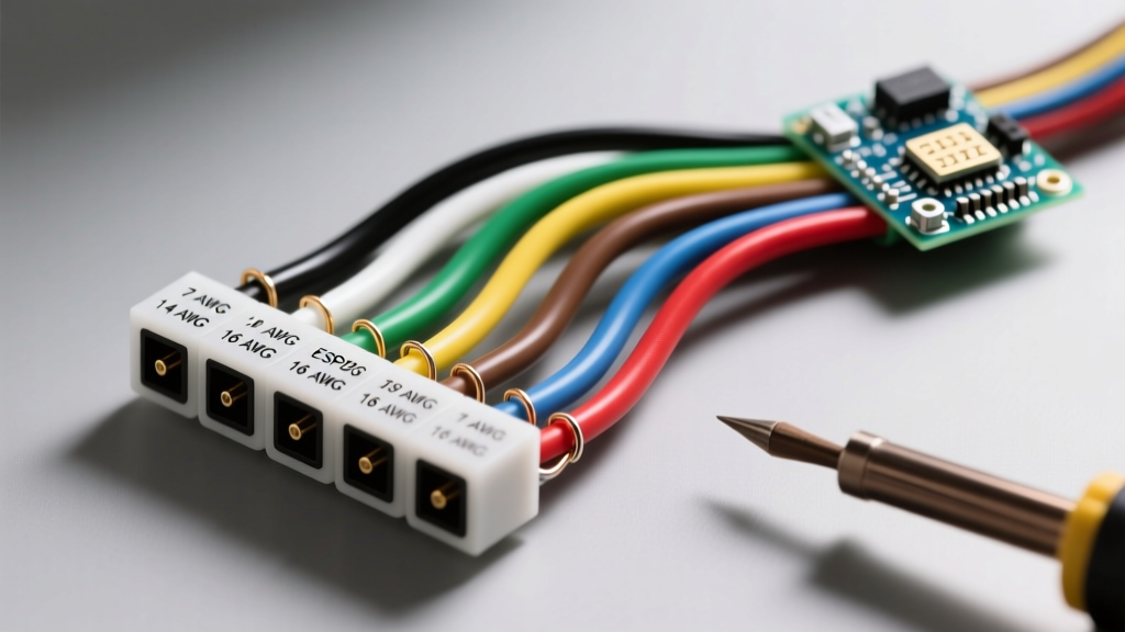
Gauge Selection: For Initiating Device Circuits (IDC), 18 AWG stranded copper is typically sufficient for runs under 500 feet. However, for Notification Appliance Circuits (NAC) powering 24VDC strobes and horns, voltage drop is a critical failure point. Strobes draw high peak currents (up to 150mA per flash). We mandate 14 AWG stranded FPLP for all NAC runs to ensure the voltage at the furthest appliance never drops below the 16VDC minimum threshold required by NFPA 72.
Expert Insight: Always use stranded copper wire for fire alarm terminations. Solid copper wire is prone to breaking under the screw terminals of detector bases due to building vibration and thermal expansion, leading to intermittent 'Open Circuit' troubles.
Step-by-Step Wiring Walkthrough
Step 1: Panel Mounting, Grounding, and Battery Connection
Mount the SK-4 cabinet to a structural wall using 1/4-inch lag screws. Fire alarm panels must have a dedicated, non-switched 120VAC circuit. Connect the AC power to the panel's transformer, but do not energize it yet.
Next, establish a dedicated earth ground. Run a 12 AWG green ground wire from the panel's ground stud to the building's main grounding electrode system. A poor ground is the leading cause of phantom alarms and lightning-induced board failures. Finally, connect the 12VDC 7Ah sealed lead-acid backup batteries in series to achieve the required 24VDC standby, but leave the final battery jumper disconnected until all field wiring is complete.
Step 2: Wiring the Initiating Device Circuits (IDC)
The IDC loop connects smoke detectors, heat detectors, and manual pull stations. The SK-4 supports up to 20 two-wire smoke detectors per zone.
- Start at the Panel: Route your 18 AWG FPLR cable from the panel's Zone 1 IDC terminals (+ and -). Polarity matters for 2-wire smoke detectors.
- Daisy-Chain the Devices: Run the wire to the first System Sensor AB-2W base. Connect the positive wire to terminal 1 and negative to terminal 2. Continue from terminal 3 and 4 to the next device.
- Manual Pull Stations: Wire pull stations at the very end of the loop or on a dedicated zone. Pull stations are dry-contact normally-open (N/O) switches. When activated, they short the circuit, dropping the loop resistance to near zero, which the panel interprets as an alarm.
Step 3: Wiring the Notification Appliance Circuits (NAC)
NAC circuits power the horns and strobes. These must be wired in parallel, but the physical wiring path is a daisy-chain loop that terminates at the panel.
- Panel Termination: Connect 14 AWG FPLR wire to the NAC 1 terminals on the SK-4 board.
- Appliance Polarity: System Sensor SPSRL-W strobes are strictly polarized. Connect the positive feed to the '+' terminal and negative to the '-' terminal on the strobe. Reversing polarity will prevent the strobe from flashing because of the internal supervisory diode, though the horn may still sound during an alarm.
- Current Calculations: Ensure the total peak current draw of all appliances on NAC 1 does not exceed the panel's 3.0 Amp limit. If your calculation exceeds 2.5 Amps, you must add a separate NAC power expander module.
Step 4: End-of-Line (EOL) Resistor Installation
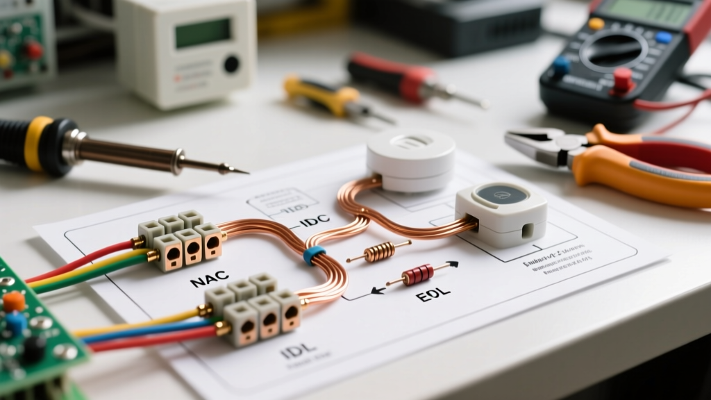
This is the most critical step in the entire wiring diagram for conventional fire alarm system deployments. The panel supervises the wiring integrity by sending a small micro-amp current through the loop. The EOL resistor at the very last physical device on the line completes the circuit.
- IDC Supervision: Install the 5.6K ohm (1/2 watt) resistor across the terminals of the last smoke detector base or pull station. If a wire breaks, the panel sees infinite resistance and triggers a 'Trouble' signal. If wires short together, the panel sees 0 ohms and triggers an 'Alarm'.
- NAC Supervision: Install the 5.6K ohm EOL resistor at the last strobe/horn. Modern codes require NAC circuits to be supervised so you know if a notification appliance wire is severed before a fire actually occurs.
Warning: Never install the EOL resistor at the panel terminals. Doing so defeats the purpose of supervising the field wiring.
Troubleshooting Common Ground Faults and Open Circuits
Once all wiring is complete, connect the battery jumper, energize the 120VAC breaker, and power up the panel. If the panel does not show a clean 'Green Power' LED, use this diagnostic framework:
1. Ground Fault (Yellow LED + Buzzer)
A ground fault occurs when a bare wire or a pinched conductor touches the metal backbox, conduit, or building steel. The SK-4 actively monitors for any voltage leakage to earth ground.
- Diagnostic Step: Power down the panel. Set your Fluke 117 multimeter to the Ohms (Ω) setting. Measure resistance between the IDC/NAC positive wires and the grounded metal cabinet. A reading below 50K ohms indicates a ground fault.
- Resolution: Inspect all device backboxes. Look for wires pinched by the mounting screws of the detector bases or pull stations. Use electrical tape or wire loom to protect conductors entering metal boxes.
2. Open Circuit Trouble on Zone 1
The panel cannot 'see' the EOL resistor. This means the circuit is broken somewhere between the panel and the last device.
- Diagnostic Step: Go to the last device on the zone. Remove the EOL resistor and measure its resistance (should be exactly 5.6K ohms). Next, measure the continuity of the wire loop back to the panel. If continuity is broken, check the wire nuts in the ceiling junction boxes. Vibration from HVAC systems often pulls loosely twisted stranded wires out of wire nuts.
3. False Alarms During HVAC Startup
If the system triggers an alarm when the building's large AC compressors kick on, you are experiencing Electromagnetic Interference (EMI) or a voltage spike.
- Resolution: Ensure your FPL wiring is routed at least 18 inches away from high-voltage AC conduits and heavy motor contactors. If parallel routing is unavoidable, cross the fire alarm wire at a strict 90-degree angle to minimize inductive coupling.
Final Inspection and NFPA 72 Handover
Before calling the local Authority Having Jurisdiction (AHJ) for inspection, perform a full 100% device test. Spray aerosol smoke into every detector to verify the exact zone maps correctly to the panel's annunciator. Trip every pull station and verify the NAC strobes achieve the required candela output and temporal-3 (T-3) horn pattern. Document all test results on the NFPA 72 standard inspection form, leaving a copy in the panel cabinet for future maintenance technicians.