
Treating Trailer Brakes as High-Draw DC Appliances
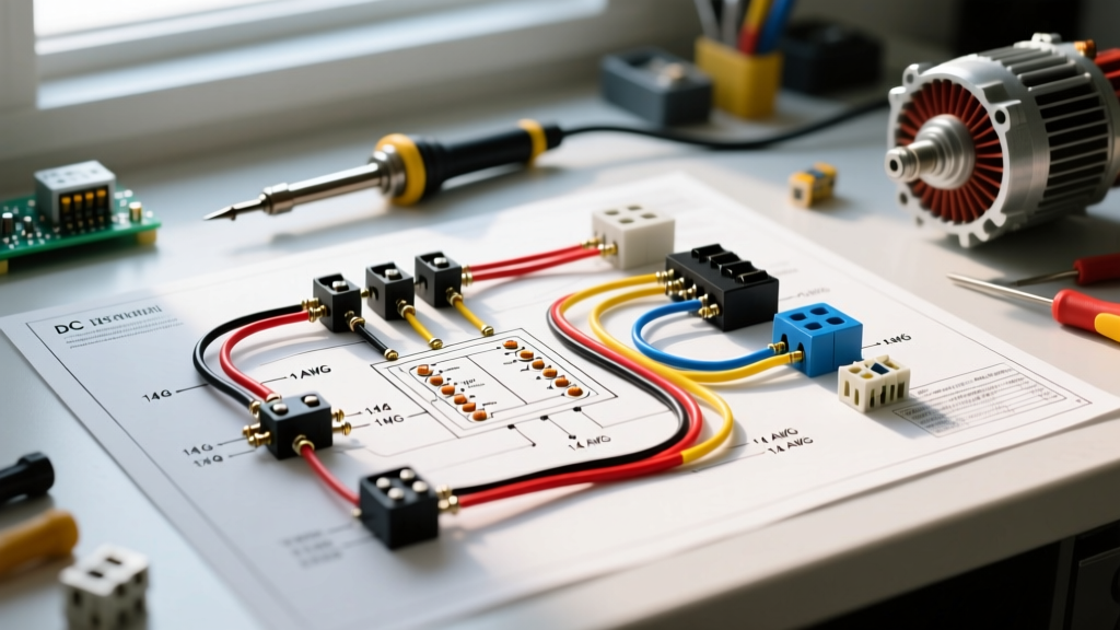
In the realm of mobile electrical systems, a trailer’s electric brake network operates much like a high-draw residential appliance. Just as you would never wire a 240V electric dryer with undersized lamp cord, you cannot safely wire electric trailer brakes with sub-standard automotive primary wire. When we approach an electric brakes wiring diagram from an appliance installation perspective, we focus on three critical pillars: dedicated circuit sizing, smart-switch control modules (brake controllers), and fail-safe grounding.
The brake controller acts as the variable transformer and smart switch, while the electromagnetic drum brakes on the trailer act as the inductive load. In 2026, with modern tow vehicles utilizing complex CAN-bus systems and pulse-width modulation (PWM), treating this wiring harness with the same rigor as a home appliance circuit is the only way to prevent voltage drop, overheated plugs, and catastrophic towing failures.
The Anatomy of a 7-Pin Electric Brakes Wiring Diagram
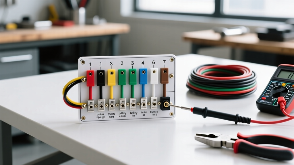
The standard 7-way RV blade connector is the 'power cord' for your trailer's electrical appliances. Understanding the SAE (Society of Automotive Engineers) standard color codes and wire gauge requirements is the first step in a safe installation. Below is the definitive pinout matrix for a standard 7-pin receptacle.
| Pin Position | Function (Appliance Equivalent) | Standard Wire Color | Minimum Wire Gauge |
|---|---|---|---|
| Pin 1 (Ground) | System Ground / Neutral Return | White | 8 AWG or 10 AWG |
| Pin 2 (Electric Brakes) | Primary High-Draw Load Circuit | Blue | 10 AWG (XLPE) |
| Pin 3 (Tail/Running Lights) | Low-Draw Illumination Circuit | Brown | 14 AWG |
| Pin 4 (12V Auxiliary) | Accessory Power / Battery Charging | Black or Red | 10 AWG or 12 AWG |
| Pin 5 (Right Turn/Stop) | Signal Circuit | Green | 14 AWG |
| Pin 6 (Left Turn/Stop) | Signal Circuit | Yellow | 14 AWG |
| Pin 7 (Center/Reverse) | Reverse Lockout / Aux Load | Purple | 14 AWG |
Expert Insight: Never rely on the trailer's chassis for the primary ground return. According to Recreational Vehicle Industry Association (RVIA) standards, a dedicated white ground wire running from the trailer tongue directly to the tow vehicle's battery negative terminal or main chassis ground stud is mandatory to prevent ground loop interference and voltage starvation at the brake magnets.
Selecting the Control Module: 2026 Market Leaders
The brake controller is the brain of the operation. Older time-delayed controllers are essentially simple rheostats, but modern proportional controllers use 3-axis accelerometers and PWM to deliver smooth, appliance-like power regulation. Here is how the two top-tier modules compare for DIY installers in 2026.
Tekonsha Prodigy P3 vs. Redarc Tow-Pro Elite V3
| Feature | Tekonsha Prodigy P3 | Redarc Tow-Pro Elite V3 |
|---|---|---|
| Retail Price (Approx.) | $175 - $195 | $235 - $255 |
| Control Type | Proportional (Inertia-based) | Proportional & User-Switchable |
| Mounting Constraints | Must be mounted within a strict 70-degree vertical arc | Knob can be mounted anywhere; main unit hidden out of sight |
| Diagnostic Output | LCD Screen with specific text codes | RGB LED Knob (Color-coded pulses) |
| Best For | DIYers who want an easy-to-read dash display | Custom dash integrations and clean, minimalist cabins |
Step-by-Step Wiring Execution: Tow Vehicle Side
Wiring the 'appliance' into your tow vehicle requires bypassing the vehicle's sensitive CAN-bus wiring wherever possible. We recommend using a dedicated wiring harness rather than splicing into factory tail light wires.
- Run the Main Power Feed: Route a 10 AWG black wire from the positive terminal of the vehicle's battery to the brake controller's power input. Install a 40-amp auto-reset circuit breaker (such as a Bussmann HWB18) within 6 inches of the battery positive post. This acts as your main appliance disconnect and short-circuit protector.
- Establish the Ground: Connect the controller's white wire to a clean, bare-metal point on the vehicle's chassis, or route it directly to the battery negative. Use a ring terminal with a star washer to bite through paint and ensure a milliohm-level resistance connection.
- Tap the Stoplight Switch: The red wire on the controller requires a 12V signal only when the brake pedal is depressed. Using a digital multimeter, probe the wires at the brake pedal switch. Find the wire that shows 0V at rest and 12V when pressed. Use a heat-shrink solder-seal butt connector to tap this wire—never use 'scotch-lok' tap connectors, which are notorious for corrosion and vibration failure.
- Route the Output to the 7-Pin: Connect the controller's blue output wire to the blue wire leading to the 7-pin receptacle's Pin 2. Ensure this wire is loomed and protected from exhaust heat and moving drivetrain components.
Trailer Side Integration: Magnets and Breakaway Switches
On the trailer side, the electric brake magnets act as the heating elements in our appliance analogy. When 12V is applied, the electromagnet engages the drum, creating friction. Because these magnets can draw up to 3.5 to 4 amps each, a tandem-axle trailer with four brakes will pull roughly 14 to 16 amps under full lock.
The Breakaway Switch: This is a critical secondary safety appliance. If the trailer detaches, a lanyard pulls a pin from a switch mounted on the trailer tongue. This switch wires directly between the trailer's 12V battery and the brake magnets, bypassing the tow vehicle entirely. It must be wired with 10 AWG wire and should have its own dedicated 20-amp inline fuse. For deep-dive schematics on integrating breakaway kits with auxiliary charging circuits, etrailer's comprehensive wiring database remains the gold standard reference for RV technicians.
Diagnostic Matrix: Troubleshooting Common Failure Modes
When your brake controller throws an error code, it is communicating a specific fault in the appliance circuit. Below is a diagnostic matrix for the most common PWM controller error codes and their physical root causes.
| Display Code / LED | Meaning | Root Cause & Edge Cases | Corrective Action |
|---|---|---|---|
| S.H. / Red Flash | Short to Ground | The blue output wire is pinched against the chassis, or a brake magnet has internally shorted to the backing plate. | Disconnect the trailer. Test the blue wire at the plug. If the short persists, the fault is in the tow vehicle wiring. If it clears, inspect trailer magnets and wiring. |
| O.L. / Yellow Flash | Overload | Current draw exceeds the controller's limit (usually >18A). Often caused by seized brake shoes or wiring multiple trailers in parallel. | Check for mechanical binding in the brake drums. Verify you are not exceeding the controller's rated axle count. |
| P.L. / Green Pulse | Power Interruption | Voltage drop on the main power feed or a loose ground connection causing the controller to reboot during high-draw braking. | Perform a voltage drop test across the main power and ground wires under load. Clean chassis ground points. |
Final Verification and Voltage Drop Testing
Before taking your rig on the highway, you must perform a voltage drop test. According to Tekonsha's official installation resources, the voltage at the trailer plug should not drop more than 0.5 volts compared to the voltage at the controller's output terminal when the manual override is fully engaged.
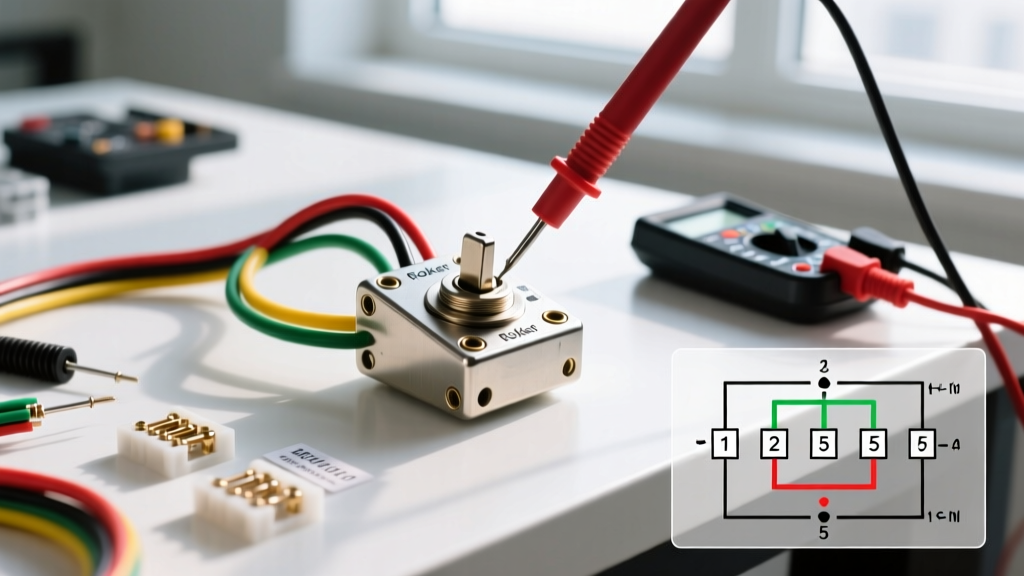
Set your multimeter to DC Volts. Place the positive probe on Pin 2 (Brakes) and the negative probe on Pin 1 (Ground) at the trailer side of the plug. Have an assistant pull the manual override lever on the controller. If you read 11.8V at the controller but only 9.5V at the trailer plug, you have excessive resistance. This 'appliance' is being starved of power, which will result in weak braking and overheated wires. Upgrade to a heavier gauge wire or replace corroded terminals immediately.
By treating your electric brakes wiring diagram as a rigorous appliance installation—prioritizing dedicated circuits, proper overcurrent protection, and low-resistance grounds—you ensure that your towing setup remains safe, responsive, and compliant with modern highway safety standards.