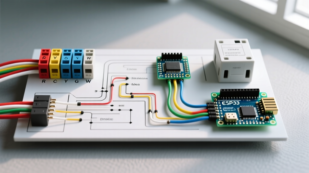

Decoding the Standard Wiring Diagram for a Thermostat
Whether you are upgrading to a Wi-Fi-enabled smart climate control system or troubleshooting a dead furnace, understanding the standard wiring diagram for a thermostat is the foundational skill of residential HVAC electrical work. Unlike line-voltage systems that directly power baseboard heaters, the vast majority of central forced-air systems rely on a low-voltage control circuit. In this comprehensive guide, we will break down the exact terminal designations, real-world wiring scenarios, and critical failure modes associated with modern 24-volt thermostat wiring.
At its core, a standard thermostat does not supply power to your HVAC equipment; it merely acts as a series of automated switches. The actual power originates from a Class 2 step-down transformer located inside your air handler or furnace, which converts 120VAC line voltage down to a safe 24VAC. When you read a wiring diagram for a thermostat, you are essentially mapping out how to close specific 24V circuits to trigger relays on the main control board.
The 24VAC Control Circuit: How the Diagram Flows
Before touching any wires, it is vital to understand the flow of electricity in a standard 18 AWG, 5-conductor or 8-conductor thermostat cable. The 24VAC 'Hot' leg leaves the transformer and travels to the R (or Rc/Rh) terminal on the thermostat. From there, internal relays route the voltage back down the cable through specific 'return' wires (W, Y, G, etc.) to the corresponding terminals on the HVAC control board. Completing this circuit energizes the specific contactor or blower relay.
Expert Safety Warning: Always shut off the dedicated 15A or 20A breaker feeding your air handler/furnace before removing the thermostat faceplate. While the thermostat wires are low voltage, the main control board houses exposed 120V line voltage that can be lethal. Furthermore, failing to kill the power is the leading cause of blown control board fuses during installation.
Universal Thermostat Terminal Reference Chart
The following table outlines the industry-standard terminal codes you will find on almost every wiring diagram for a thermostat, from basic Honeywell non-programmable models to advanced ecobee smart thermostats.
| Terminal | Standard Wire Color | Function | System Application |
|---|---|---|---|
| R (or Rc/Rh) | Red | 24VAC Power (Hot) | All Systems |
| C | Blue or Black | 24VAC Common (Return) | Smart Thermostats / AC |
| W (or W1) | White | Primary Heat Stage 1 | Gas, Oil, Electric, Heat Pump |
| Y (or Y1) | Yellow | Primary Cool Stage 1 | Central AC, Heat Pump |
| G | Green | Indoor Blower Fan | All Forced Air Systems |
| O / B | Orange / Dark Blue | Reversing Valve | Heat Pumps Only |
| Aux / E | Brown or Black | Auxiliary / Emergency Heat | Heat Pumps with Strip Heat |
Scenario 1: Conventional 1-Stage Heat / 1-Stage Cool
The most common residential setup in North America is a conventional split system (gas furnace + outdoor AC condenser). The wiring diagram for a thermostat in this scenario requires a minimum of four wires, though five is highly recommended to support the C-terminal.
- Red to R: Provides the 24V source.
- White to W: Closes the circuit to the gas valve and inducer motor relay for heating.
- Yellow to Y: Closes the circuit to the outdoor condenser contactor for cooling.
- Green to G: Closes the circuit to the indoor blower fan relay.
- Blue to C: Completes the 24V circuit to provide continuous power to the thermostat's Wi-Fi radio and display.
Scenario 2: Heat Pump Systems and the O/B Dilemma
Heat pumps introduce a unique complexity to the thermostat wiring diagram: the reversing valve. This valve physically changes the direction of refrigerant flow to switch between heating and cooling modes. However, not all manufacturers energize this valve the same way, leading to a massive point of failure for DIY installers.
- The 'O' Terminal (Cooling Energized): Brands like Carrier, Trane, Lennox, and Mitsubishi energize the reversing valve in the cooling mode. If you have one of these, the orange wire connects to the O terminal.
- The 'B' Terminal (Heating Energized): Brands like Rheem, Ruud, and Goodman energize the valve in the heating mode. The dark blue (or sometimes orange) wire connects to the B terminal.
Failure Mode: If you wire a Rheem heat pump to the O terminal instead of B, the system will blow cold air when you call for heat, and hot air when you call for AC. The fix is simply moving the wire to the correct terminal and adjusting the 'O/B' setup parameter in the thermostat's installer menu.
The C-Wire Dilemma in Modern Smart Thermostats
According to the Department of Energy, smart thermostats can significantly reduce annual heating and cooling costs. However, premium models like the 4th Gen Nest Learning Thermostat ($279) or the ecobee SmartThermostat ($249) require a continuous 24VAC power supply to run their displays, sensors, and Wi-Fi antennas.
If your current wiring diagram lacks a C-wire (Common), the smart thermostat will attempt to 'steal' power by passing a small trickle of current through the Y (cooling) or W (heating) circuits. This causes several severe edge-case failures:
- Contactor Chatter: The stolen voltage is enough to weakly pull in the outdoor AC contactor, causing it to rapidly click on and off, eventually welding the contacts shut and destroying the compressor.
- Phantom Heating: Trickle current through the W wire can inadvertently activate a gas valve relay or electric strip heat.
- Wi-Fi Drops: The thermostat will reboot constantly when the HVAC system kicks on, dropping it from your network.
The Solution: If your thermostat cable only has 4 wires, pull a new 18/5 cable. If pulling wire is impossible through finished walls, install a 24V C-Wire Adapter (typically $15-$25) at the air handler. This device plugs into the control board and uses the existing unused wires to multiplex the power and data signals.
Critical Failure Modes & Troubleshooting
When an HVAC system fails to respond to the thermostat, the issue is rarely the thermostat itself. Use these expert troubleshooting steps to diagnose the control circuit:
1. The Blown 3A Control Board Fuse
Almost all modern furnace control boards feature a 3-amp ATO (automotive-style) blade fuse, usually colored purple. If a bare R wire accidentally touches the grounded metal chassis of the air handler or the C wire while the power is on, it creates a dead short. This instantly blows the 3A fuse to protect the $150+ control board transformer. Fix: Replace the fuse with an exact 3A equivalent (never upsize to a 5A fuse, or you risk burning out the transformer windings).
2. Voltage Drop Over Long Wire Runs
Standard 18 AWG solid copper thermostat wire is rated for standard residential runs up to 100 feet. If your thermostat is located in a detached garage or an extreme end of a large estate (runs exceeding 150 feet), the resistance of the 18 AWG wire will cause a voltage drop. The 24VAC may drop below 19V at the thermostat, causing smart screens to flicker and relays to fail to engage. Fix: Upgrade the run to 16 AWG or 14 AWG thermostat wire to reduce resistance.
Code Compliance and Safety Standards
When installing or modifying thermostat wiring, compliance with the National Electrical Code (NEC) is mandatory. According to NFPA 70 (NEC) Article 725, thermostat wiring is classified as a Class 2 circuit. This classification dictates that the low-voltage thermostat cable must be physically separated from line-voltage (120V/240V) wiring by at least 2 inches, or separated by a continuous and firmly fixed nonconductor (like a conduit or wooden runner). Never run 18 AWG thermostat wire inside the same junction box or conduit as 120V Romex, as a short between the two could send lethal line voltage directly to the thermostat faceplate.
By understanding the exact flow of the 24V circuit, respecting terminal designations, and adhering to Class 2 wiring standards, you can confidently install, upgrade, and troubleshoot any residential climate control system on the market.