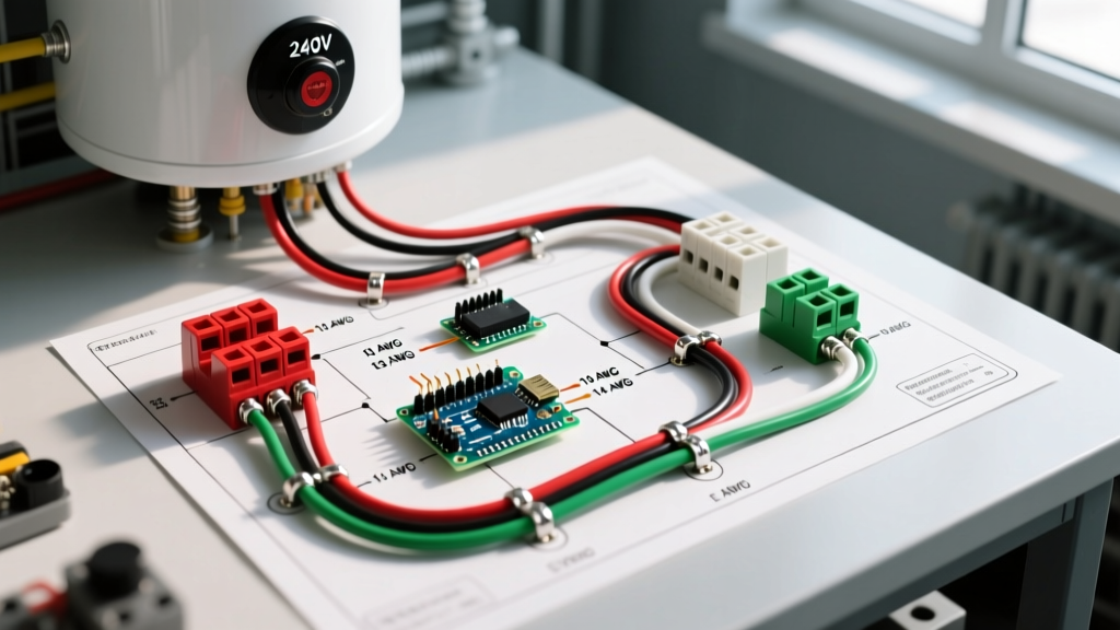

Understanding the 240V Hot Water Heater Electric Wiring Diagram
Wiring a standard 240-volt electric storage tank water heater requires strict adherence to the National Electrical Code (NEC) and a clear understanding of high-voltage circuitry. Unlike 120V household circuits, a 240V circuit utilizes two hot legs and a dedicated equipment grounding conductor—no neutral wire is required for standard resistive element heaters. This comprehensive walkthrough decodes the hot water heater electric wiring diagram, guiding you from the main breaker panel to the internal thermostat terminals.
According to the National Fire Protection Association (NFPA), electrical failures in water heating equipment are a leading cause of residential fires when circuits are improperly sized or grounded. Whether you are installing a standard 40-gallon Rheem PROE40 T2 RH95 or a 50-gallon Bradford White RE350T6, the fundamental wiring principles remain identical.
NEC Sizing Rules: Breaker and Wire Gauge Matrix
Before touching a single wire, you must calculate the correct branch circuit size. NEC Article 422.13 mandates that storage-type water heaters with a capacity of 120 gallons or less must be considered a continuous load for sizing purposes, meaning the branch circuit must be rated at 125% of the heater's nameplate wattage.
| Element Wattage | Voltage | Amperage Draw | 125% NEC Calculation | Min. Breaker Size | Min. Copper Wire Gauge (NM-B / THHN) |
|---|---|---|---|---|---|
| 3000W | 240V | 12.5A | 15.6A | 2-Pole 20A | 12 AWG (12/2) |
| 3800W | 240V | 15.8A | 19.7A | 2-Pole 20A | 12 AWG (12/2) |
| 4500W | 240V | 18.75A | 23.4A | 2-Pole 25A or 30A | 10 AWG (10/2) |
| 5500W | 240V | 22.9A | 28.6A | 2-Pole 30A | 10 AWG (10/2) |
Note: While a 25A breaker is technically compliant for a 4500W heater, 30A 2-pole breakers (like the Square D QO230 or Eaton BR230) are the industry standard due to widespread availability and future-proofing.
Tools and Materials Required
- Voltage Tester: Fluke 1AC-II or Klein NCVT-4 (Non-Contact) plus a digital multimeter for confirmation.
- Cable: 10/2 NM-B (Romex) for indoor, dry, exposed runs, OR 10 AWG THHN/THWN wires pulled through 1/2-inch Liquidtight Flexible Metal Conduit (LFMC) for damp areas or physical protection.
- Breaker: 30-Amp 2-pole HACR type circuit breaker matching your panel brand.
- Connectors: 1/2-inch NM cable connectors or LFMC fittings, plus appropriate wire nuts (e.g., Ideal Twister 341 or 3M Scotchlok).
- Torque Screwdriver: Calibrated to 12-15 in-lbs for terminal screws.
Step-by-Step Wiring Walkthrough
Step 1: Main Panel Preparation and Lockout
Safety is non-negotiable. Shut off the main breaker to de-energize the panel bus bars. Verify the absence of voltage using a multimeter across the main lugs. Install the 30A 2-pole breaker into an available dual slot. Snap it firmly into the bus bar stab; it should click securely into place.
Step 2: Routing the Cable and Conduit
Run your 10/2 NM-B cable from the panel to the water heater location. If local codes require physical protection (common in garages or unfinished basements), transition to 1/2-inch LFMC for the final 3 to 6 feet leading to the heater's junction box. Secure the cable or conduit with straps every 4.5 feet per NEC Article 334.15.
Step 3: Wiring the Panel Connections
Strip back the cable sheathing, leaving at least 1/4 inch of insulation on the individual conductors.
- Leg 1 (Black): Connect to the first terminal on the 2-pole breaker.
- Leg 2 (White): Because this is a 240V circuit, the white wire is used as a second hot leg. You must re-identify it by wrapping it with black or red electrical tape at both ends. Connect to the second breaker terminal.
- Ground (Bare/Green): Terminate on the panel's equipment grounding bus bar. Never land a ground wire on the neutral bus bar in a subpanel, though they are bonded in the main service panel.
Step 4: The Heater Junction Box
Open the junction box cover on the top or side of the water heater. Feed your cable through the 1/2-inch knockout using a proper cable connector—never let raw cable sheathing rest against sharp metal knockouts.
- Wire-nut the black panel wire to the black heater wire.
- Wire-nut the re-identified white panel wire to the red (or white) heater wire.
- Create a pigtail using a 10 AWG bare copper wire. Connect the panel ground, the heater ground, and the pigtail together with a wire nut. Terminate the other end of the pigtail to the green grounding screw inside the junction box. This ensures the metal chassis of the tank is bonded to the earth ground.
Internal Diagram: Thermostats and Elements
Most residential 240V water heaters utilize a non-simultaneous dual-element system. This means the upper and lower elements never draw power at the exact same time, which is why a 4500W heater only requires a 30A circuit rather than a 60A circuit.
- Upper Thermostat Logic: When the tank is cold, the upper thermostat receives 240V from the junction box. It powers the upper element until the top third of the tank reaches the set temperature (usually 120°F).
- Transfer Switch: Once the upper thermostat is satisfied, it internally switches the 240V feed down to the lower thermostat.
- Lower Thermostat Logic: The lower thermostat then powers the lower element to heat the remaining water. If the upper thermostat detects a temperature drop (due to heavy hot water usage), it immediately cuts power to the lower element and prioritizes the upper element again.
Edge Case Warning: If you are wiring a specialty 'Simultaneous' or 'Continuous' high-recovery commercial unit, both elements run at once. This requires completely different wire sizing (often 8 AWG or 6 AWG) and a much larger breaker. Always verify the schematic on the inside of the heater's access panels.
Crucial Testing and Energizing Sequence
CRITICAL WARNING: The Dry-Fire Rule
Never energize a 240V water heater before the tank is 100% full of water. Exposed heating elements will reach 1400°F and melt their internal nichrome wire in less than 30 seconds if fired in the air. This voids all manufacturer warranties.
Follow this exact sequence to commission the unit:
- Close the heater's drain valve.
- Open a hot water faucet at the highest point in the house (e.g., an upstairs bathroom) to allow air to escape.
- Turn on the cold water supply valve to the heater.
- Wait until a steady, uninterrupted stream of water flows from the open hot water faucet. This confirms the tank is completely full and purged of air.
- Close the faucet.
- Turn on the 30A 2-pole breaker at the main panel.
- Use your multimeter to verify 240V across the two hot wires at the junction box.
Troubleshooting Common Wiring Failures
Even with a perfect hot water heater electric wiring diagram execution, issues can arise. Here is how to diagnose them based on the U.S. Department of Energy's efficiency and maintenance guidelines:
- Breaker Trips Immediately: This almost always indicates a short circuit or a grounded element. Turn off power, remove the access panels, and test the resistance of the elements to the tank chassis. A reading of anything less than infinite (OL) means the element's internal sheath has ruptured and it must be replaced.
- Heater Runs but Never Gets Hot: Check the high-limit reset button (ECO) located on the upper thermostat. If it has tripped, press it firmly until it clicks. If it trips again immediately, the lower thermostat is likely stuck in the 'closed' position, causing both elements to run simultaneously and overheat the tank.
- Water is Too Hot / Scalding: Verify that the wire connections on the thermostat terminal screws are tight. A loose connection creates high resistance, generating localized heat that tricks the thermostat's bimetallic sensor into thinking the water is colder than it actually is, causing it to run continuously.
Final Code and Safety Considerations
Always consult your local Authority Having Jurisdiction (AHJ). While the NEC provides the baseline, local municipalities may have specific amendments regarding water heater strapping (for seismic zones), expansion tanks (for closed-loop plumbing systems), and disconnect switches. The Consumer Product Safety Commission (CPSC) strongly recommends that any 240V hardwired appliance installation be inspected by a licensed electrical professional if you are not entirely confident in your termination torque and grounding continuity. Proper execution of this wiring diagram ensures a safe, efficient, and long-lasting hot water supply for your home.