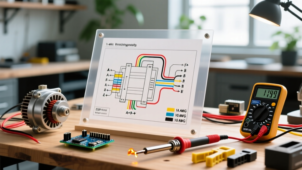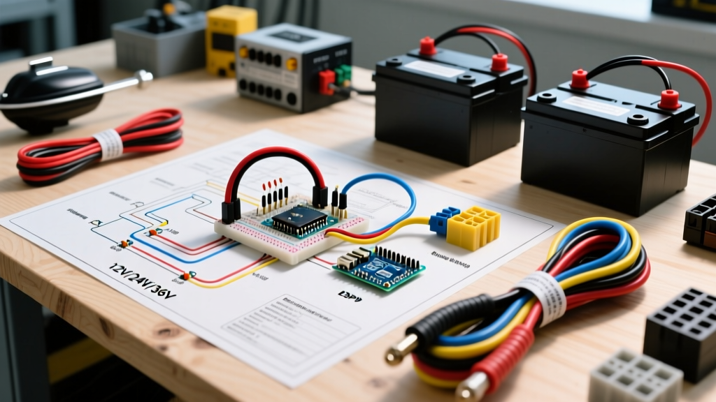

Mastering the Wiring Diagram for Trolling Motor Marine Setups
Whether you are rigging a 2026 bass boat with a brushless Garmin Force Kraken or outfitting a pontoon with a 36V Minn Kota Ultrex MDI, understanding the correct wiring diagram for trolling motor applications is non-negotiable. A flawed marine electrical setup does not just result in poor runtime; it causes catastrophic voltage drops, melted Anderson plugs, and in worst-case scenarios, electrical fires on the water. According to the American Boat & Yacht Council (ABYC) E-11 standards, marine DC electrical systems demand specific overcurrent protection, wire sizing, and environmental sealing that standard automotive wiring simply cannot provide.
In this vehicle-specific guide, we break down the exact wiring topologies for 12V, 24V, and 36V marine battery banks, complete with wire gauge matrices, circuit breaker sizing, and professional-grade termination techniques to ensure your trolling motor performs flawlessly in harsh aquatic environments.
Core Components of a Marine Trolling Motor Circuit
Before diving into the specific voltage diagrams, you must source marine-grade components. Using automotive copper wire on a boat is a primary failure point due to 'black wire corrosion'—a phenomenon where moisture wicks through the wire insulation and oxidizes the copper strands from the inside out.
- Wire: Always use Type 3 stranding, tinned marine-grade copper wire (e.g., Ancor or Windy Nation). The tin coating prevents oxidation and handles the vibration of a boat hull.
- Overcurrent Protection: A resettable circuit breaker or ANL fuse must be installed on the positive lead within 7 inches of the battery terminal, per ABYC E-11 guidelines.
- Connectors: For quick disconnects, use heavy-duty Marinco trolling motor plugs or Anderson Powerpole SB175 connectors. Standard 12V automotive quick-disconnects will melt under a 50A continuous load.
- Terminations: Use adhesive-lined (dual-wall) heat shrink terminals. The inner meltable adhesive creates a waterproof seal that blocks moisture migration.
Wire Gauge and Circuit Breaker Sizing Matrix
Wire sizing is dictated by the maximum amperage draw of the motor and the total length of the wire run (from the battery bank to the motor head and back). The Blue Sea Systems wire sizing guide emphasizes keeping voltage drop below 3% for critical electronics and below 10% for motors. Below is the definitive matrix for modern 2026 trolling motors.
| System Voltage | Max Thrust | 2026 Motor Example | Max Draw | Wire Gauge (Up to 15ft) | Wire Gauge (15-22ft) | Breaker Size |
|---|---|---|---|---|---|---|
| 12V | 55 lbs | Newport Vessels 55lb | 52A | 8 AWG | 6 AWG | 60A |
| 24V | 80 lbs | Garmin Force Kraken | 56A | 6 AWG | 4 AWG | 70A |
| 36V | 112 lbs | Minn Kota Ultrex MDI | 52A | 6 AWG | 4 AWG | 60A |
Pro Tip: If your wire run exceeds 22 feet (common on large center-console or pontoon boats), you must step up to 2 AWG marine wire to prevent severe voltage drop, which robs your motor of torque and drastically reduces battery life.
12V Trolling Motor Wiring Diagram (Kayaks & Small Skiffs)
A 12V system is the simplest topology, typically powering 45lb to 55lb thrust motors on kayaks, jon boats, and small skiffs. It requires a single 12V deep-cycle AGM or Lithium Iron Phosphate (LiFePO4) battery.
Step-by-Step 12V Routing
- Connect the Positive (Red) trolling motor lead to the positive terminal of the 12V battery.
- Install a 60A inline circuit breaker on this positive lead, positioning it as close to the battery terminal as physically possible (maximum 7 inches).
- Connect the Negative (Black) trolling motor lead directly to the negative terminal of the battery.
- Secure all connections with a nut and lock washer, then cover the terminals with insulating boots to prevent accidental shorting against the bilge or hull.
24V Series Wiring Diagram (Bass Boats & Medium Pontoons)
Most modern brushless motors, like the Lowrance Ghost or Garmin Force, operate on a 24V system to deliver 80+ lbs of thrust while keeping amperage draw manageable. This requires two 12V batteries wired in series to double the voltage while maintaining the same amp-hour (Ah) capacity.
Step-by-Step 24V Series Routing
- Place two 12V marine batteries in your battery box. We will call them Battery A and Battery B.
- Using a heavy-duty 4 AWG jumper wire, connect the Negative (-) terminal of Battery A to the Positive (+) terminal of Battery B. This is the series bridge.
- Connect the Positive (Red) trolling motor lead to the remaining open positive terminal (Battery B).
- Install a 70A circuit breaker on this positive lead, within 7 inches of Battery B's terminal.
- Connect the Negative (Black) trolling motor lead to the remaining open negative terminal (Battery A).
Crucial Note: Never connect a 12V accessory (like a fish finder or bilge pump) across the 24V series bridge. Always tap 12V accessories from a single battery or use a dedicated DC-DC step-down converter to avoid unbalancing the battery bank.
36V High-Thrust Wiring Diagram (Offshore & Large Pontoons)
For massive vessels or heavy current conditions, a 36V system pushing 112 lbs of thrust (such as the Minn Kota Ultrex) is required. This utilizes three 12V batteries wired in series to produce 36V nominal (often reading 38.4V fully charged on LiFePO4 setups).
Step-by-Step 36V Series Routing
- Align three 12V batteries: Battery A, Battery B, and Battery C.
- Install a jumper from Battery A Negative (-) to Battery B Positive (+).
- Install a second jumper from Battery B Negative (-) to Battery C Positive (+).
- Connect the trolling motor Positive (Red) lead to the open positive terminal on Battery C, ensuring a 60A or 70A breaker is inline within 7 inches.
- Connect the trolling motor Negative (Black) lead to the open negative terminal on Battery A.
For the absolute best reference on manufacturer-specific plug configurations and internal motor jumper settings, always cross-reference your physical setup with the Minn Kota official support documentation or your specific motor's user manual, as 4-wire plug receptacles require precise pin-mapping for 12V/24V/36V switching.
Professional Termination: Crimping and Sealing
The most common point of failure in any trolling motor wiring diagram is the termination point. Vibration and moisture will destroy a poorly crimped connection in a single season.
The Adhesive Heat Shrink Method
- Strip: Use a precision wire stripper to remove exactly the required length of insulation (usually 3/8 inch for 6 AWG). Do not nick the tinned copper strands.
- Crimp: Use a ratcheting hex-crimp tool (not a standard indent crimper). A hex crimp applies uniform 360-degree pressure, cold-welding the copper strands to the barrel for maximum conductivity.
- Seal: Slide dual-wall adhesive heat shrink tubing over the terminal. Apply heat evenly with a heat gun (not a lighter) until the tubing shrinks tightly and the inner adhesive oozes slightly out of the ends. This creates an IP67 waterproof seal.
Common Failure Modes & Troubleshooting
Even with a perfect wiring diagram for your trolling motor, environmental factors can degrade performance. Here is how to diagnose common issues on the water:
1. Severe Voltage Drop Under Load
If your 24V system drops below 22V when the motor is engaged at high speeds, you are experiencing voltage drop. This is usually caused by undersized wire for the run length, or corroded connections inside the Marinco plug. Fix: Test voltage directly at the motor head pins while under load. If it is significantly lower than the battery terminal voltage, upgrade your wire gauge or replace the plug receptacle.
2. Tripping Circuit Breakers
If your 60A breaker trips constantly, it could be a failing breaker (thermal fatigue from engine heat) or a binding motor prop shaft. Fix: Swap the breaker with a known good unit. If it still trips, inspect the motor's lower unit for wrapped fishing line causing mechanical resistance.
3. Black Wire Corrosion
If the copper wire turns black and brittle near the battery terminals, moisture has breached the insulation. Fix: Cut back the wire until you see bright, shiny copper, re-terminate with adhesive heat shrink, and ensure your battery box is properly ventilated to prevent corrosive off-gassing from accumulating.
Frequently Asked Questions
Can I use a single 36V lithium battery instead of three 12V batteries?
Yes. In 2026, purpose-built 36V marine lithium batteries (like those from Dakota Lithium or RELiON) are incredibly popular. They drastically reduce weight and eliminate the need for series jumper wires. When using a single 36V battery, your wiring diagram simply becomes a 12V-style setup (Positive to Positive, Negative to Negative), but you must ensure your circuit breaker and wire gauge are rated for the specific continuous amperage of your motor.
Do I need to wire my trolling motor to the boat's main ground bus?
No. Trolling motors should have a dedicated, isolated circuit running directly back to the dedicated trolling motor battery bank. Tying the trolling motor negative into the boat's main starting battery ground bus can create ground loops, introduce RF interference to your sonar units, and cause erratic motor behavior.