
Why Code Compliance is Non-Negotiable for Swamp Coolers
Evaporative coolers (commonly known as swamp coolers) present a unique electrical hazard: they intentionally combine high-volume water circulation with high-draw electric motors in damp, often outdoor, environments. A standard wiring diagram for evaporative cooler installations must strictly adhere to the National Electrical Code (NEC), specifically addressing Article 430 (Motors, Motor Circuits, and Controllers) and Article 210 (Branch Circuits). According to the U.S. Department of Energy, improper installation not only voids manufacturer warranties but drastically increases the risk of electrocution and fire.
In this comprehensive guide, we break down the exact wiring schematic, terminal mappings, and NEC sizing requirements for residential 120V and 240V evaporative coolers, ensuring your setup is safe, efficient, and fully compliant with current 2026 electrical standards.
The Master Wiring Diagram: Path from Panel to Pad
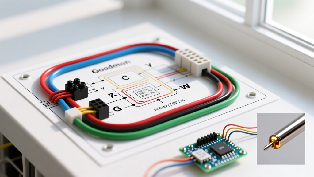
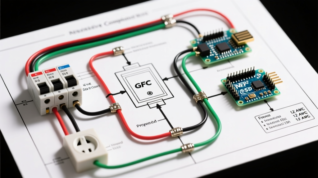
Unlike standard indoor appliances, an evaporative cooler requires an exterior disconnect, liquid-tight conduit, and specific GFCI protection. Below is the textual schematic mapping the correct sequence for a standard 120V, 1/3 HP residential unit (e.g., Hessaire or MasterCool models).
Circuit Path Sequence
- Main Service Panel: 120V, 20-Amp Single-Pole GFCI Circuit Breaker.
- Branch Circuit Wiring: 12 AWG THWN/THHN (Black, White, Green) pulled through interior walls to the exterior penetration point.
- Exterior Transition: Transition from interior wiring to Liquid-Tight Flexible Metal Conduit (LFMC) or Schedule 80 PVC using a weatherproof conduit body (LB fitting).
- Outdoor Disconnect: NEMA 3R rated, 60-Amp unfused pull-out disconnect switch mounted within sight of the cooler (NEC 430.102).
- Cooler Junction Box: 12 AWG THWN enters the factory-sealed cooler junction box via a waterproof cord grip.
- Internal Terminal Block: Connections split to the Blower Motor (High/Low/Neutral/Ground), Water Pump (Hot/Neutral/Ground), and Thermostat/Switch controls.
Critical NEC Warning (Article 334.12): You must NEVER use standard NM-B (Romex) cable for the exterior portion of an evaporative cooler circuit. NM-B is strictly prohibited in damp or wet locations. You must transition to individual THWN/THHN conductors inside a rated conduit before the wire exits the building envelope.
NEC Sizing Rules: Wire Gauge and Breaker Selection
Sizing the wire and breaker for an evaporative cooler is not based on the standard 15A/20A receptacle rules. Per NFPA 70 (NEC) Article 430.22, conductors supplying a single motor must have an ampacity of not less than 125% of the motor's Full-Load Amps (FLA). Furthermore, motor branch-circuit short-circuit and ground-fault protection devices must be sized according to Table 430.52, which often allows breakers to be sized significantly higher than the wire ampacity to accommodate motor starting inrush currents.
Evaporative Cooler Motor Sizing Matrix
| Motor Component | Horsepower (HP) | Approx. FLA (120V) | 125% NEC Ampacity | Min. Copper Wire Size | Max Standard Breaker |
|---|---|---|---|---|---|
| Water Pump | 1/40 HP | 1.2A | 1.5A | 14 AWG (12 AWG rec.) | 15A |
| Blower Motor (Small) | 1/3 HP | 4.0A | 5.0A | 12 AWG | 15A or 20A |
| Blower Motor (Med) | 1/2 HP | 5.8A | 7.25A | 12 AWG | 20A |
| Blower Motor (Large) | 3/4 HP | 7.8A | 9.75A | 10 AWG | 20A or 25A |
Note: While 14 AWG is technically legal for a 1/40 HP pump on a 15A circuit, industry best practice dictates using 12 AWG for the entire branch circuit to mitigate voltage drop over long outdoor conduit runs and to unify the circuit protection under a single 20A breaker.
GFCI and Disconnect Requirements
Water and electricity are a lethal combination. The NEC has continuously tightened GFCI (Ground-Fault Circuit Interrupter) requirements for outdoor equipment.
The GFCI Mandate
Under NEC Article 210.8(A)(3) and 210.8(F), all outdoor receptacles and equipment installed in damp/wet locations require GFCI protection. For a hardwired evaporative cooler, this means installing a GFCI Circuit Breaker in the main panel.
- The Nuisance Tripping Edge Case: Older Permanent Split Capacitor (PSC) blower motors can sometimes generate electrical noise or minor transient leaks during startup, causing sensitive GFCI breakers to trip. If you experience this, do NOT remove the GFCI protection (a severe code violation). Instead, upgrade to a newer ECM (Electronically Commutated Motor) or ensure the motor's run capacitor is not degrading, as failing capacitors often cause phase-shift leakage that trips GFCIs.
The Disconnect Requirement
Per NEC 430.102, an approved disconnecting means must be located within sight of the motor controller. For a roof-mounted or wall-mounted swamp cooler, this means a NEMA 3R weatherproof disconnect box must be mounted directly adjacent to the unit, allowing a technician to physically lock out the power before servicing the water pads or internal wiring.
Internal Terminal Mapping: Blower and Pump
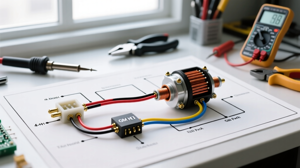
Once inside the cooler's factory junction box, the wiring splits. Most residential units utilize a rotary switch or a wall-mounted thermostat to control the pump and blower independently. Here is the standard terminal mapping for a 3-speed PSC blower motor and a synchronous water pump.
Blower Motor (PSC) Terminals
- Line (L1 / Hot): Connects to the main incoming black wire via the High/Low speed switch.
- High Speed (Usually Black wire on motor): Energized when the switch is set to 'High'.
- Low Speed (Usually Red or Blue wire on motor): Energized when the switch is set to 'Low'.
- Neutral (White): Connects directly to the incoming circuit neutral and the capacitor's common terminal.
- Ground (Green/Bare): Must be bonded to the motor chassis and the metal cooler housing using a dedicated green grounding screw.
Water Pump Terminals
- Hot (Black/Brown): Routes through the 'Pump' toggle switch before receiving line voltage.
- Neutral (White): Tied directly to the main circuit neutral.
- Ground: Bonded to the chassis.
Step-by-Step Installation & Wiring Sequence
- Lockout/Tagout (LOTO): Turn off the main breaker and apply a physical lock. Verify zero voltage with a CAT III multimeter.
- Mount the Disconnect: Secure the NEMA 3R disconnect box to the exterior wall or roof strut within 6 feet of the cooler.
- Pull Conduit & Wire: Run LFMC from the disconnect to the cooler. Pull 12 AWG THWN/THHN (Black, White, Green) through the conduit. Leave 6 inches of slack inside the junction box.
- Terminate the Disconnect: Connect the incoming hot to the line side of the disconnect, and the load side to the outgoing conduit wires. Bond the ground bar to the enclosure.
- Wire the Internal Switch: Route the incoming hot to the center terminal of the pump switch and the blower speed selector. Follow the manufacturer's specific color-code diagram for the motor pigtails.
- Seal the Junction Box: Apply dielectric grease to wire nuts, ensure no bare copper is exposed, and tightly secure the waterproof junction box lid with its factory gasket.
Common Code Violations & Troubleshooting Matrix
Even experienced DIYers make critical errors when wiring swamp coolers. Use this matrix to identify and correct common failures.
| Symptom / Failure Mode | Root Cause & Code Violation | Expert Troubleshooting & Fix |
|---|---|---|
| GFCI breaker trips instantly upon turning on the pump. | Moisture ingress in the junction box or degraded pump shaft seal causing current leakage to ground. | Inspect the junction box gasket. Replace the pump if water has breached the internal motor windings. Do not bypass GFCI. |
| Blower motor hums but will not spin. | Failing run capacitor or seized centrifugal switch. Not a wiring fault, but a component failure. | Discharge and test the run capacitor with a multimeter (should read within 5% of its microfarad rating, typically 5-10 µF). Replace if bulging or out of spec. |
| Voltage at cooler reads 112V (or lower) under load. | Undersized wire or excessively long run causing voltage drop. Violates NEC 210.19(A) informational note. | Upgrade from 12 AWG to 10 AWG copper for runs exceeding 75 feet to maintain voltage within 3% of nominal. |
| Exterior disconnect box shows rust/corrosion inside. | Using an indoor-rated (NEMA 1) box in a wet location. Violates NEC 312.2. | Replace immediately with a NEMA 3R rated enclosure and ensure conduit hubs are sealed with silicone. |
Expert Safety Checklist Before Energizing
Before removing your LOTO device and flipping the breaker, run through this final verification checklist to ensure compliance with NEMA motor safety standards and the NEC:
- [ ] Ground Continuity: Verify continuity between the main panel ground bar, the disconnect enclosure, the motor chassis, and the metal cooler housing.
- [ ] Conduit Sealing: Confirm that duct seal or silicone is applied where the conduit enters the exterior wall to prevent water and pest intrusion.
- [ ] Wire Stripping Length: Ensure no more than 1/4 inch of bare copper is exposed past the wire nut or terminal screw.
- [ ] Strain Relief: Verify that the internal flexible motor leads are secured and not resting against the rotating blower cage.
Properly wiring an evaporative cooler requires respecting the intersection of plumbing and electrical codes. By adhering to the 125% FLA sizing rule, utilizing THWN in liquid-tight conduit, and mandating GFCI protection, you ensure your cooling system operates safely through the harshest summer conditions.