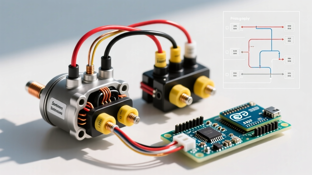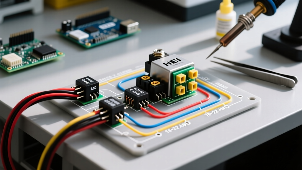

Introduction to HEI in Appliance and Industrial Applications
When retrofitting stationary industrial engines, heavy-duty generator sets, or motor-driven appliance conveyors, the GM High Energy Ignition (HEI) system remains the gold standard for reliable, high-voltage spark delivery. While often associated with classic V8 automotive swaps, the HEI distributor is fundamentally an electro-mechanical appliance component when deployed in fixed industrial environments. Understanding the exact wiring diagram for HEI distributor configurations is critical to prevent module burnout, ensure proper coil saturation, and maintain consistent timing under heavy continuous loads.
Unlike modern distributorless ignition systems (DIS) that rely on complex engine control units (ECUs), the HEI system is entirely self-contained. The ignition module, magnetic pickup, and coil-in-cap design require minimal external wiring. However, the transition from older points-style systems to HEI introduces specific electrical demands that, if ignored, will destroy a $60 to $150 ignition module within hours of operation.
The Golden Rule: Bypassing the Ballast Resistor Wire
The single most common failure point in HEI conversions is inadequate voltage supply. Pre-1974 points-style ignition systems utilized a ballast resistor or a specialized resistance wire (often a cloth-covered pink wire) to drop the system voltage from 12V down to roughly 9V during normal operation, protecting the breaker points from arcing.
The HEI system, conversely, requires a full, unimpeded 12V to 14.4V to properly saturate the internal coil and power the solid-state switching module. If you wire an HEI distributor using the factory ballast resistance wire, the module will starve for voltage. This causes the internal switching transistor to operate in its linear (active) region rather than fully saturating, generating massive amounts of heat and leading to catastrophic thermal failure.
Expert Tip: Always run a dedicated, fused 12 AWG copper wire directly from a switched 12V ignition source to the HEI cap. According to SAE J1128 standards for low-tension primary cable, 12 AWG wire safely handles the 4 to 6-amp peak current draw of the HEI coil with negligible voltage drop over standard engine bay distances.
Standard 4-Pin Wiring Diagram for HEI Distributor
The standard GM 4-pin HEI module (commonly found in crate engines like the GM Performance Parts 12344123 and aftermarket MSD 8365 conversions) utilizes a simplified wiring harness integrated directly into the distributor cap. The external connections are minimal but must be executed with precision.
Terminal Pinout Matrix
| Terminal Label | Function | Wire Gauge | Connection Destination |
|---|---|---|---|
| BATT | Primary 12V Power Input | 12 AWG | Ignition Switch (Switched 12V via 30A Fuse) |
| TACH | Tachometer Signal Output | 18 AWG | Tachometer Input / Diagnostic Scope |
| Unmarked (GND) | System Ground Reference | N/A (Internal) | Distributor Housing to Engine Block |
The grounding of the HEI system is uniquely handled through the physical mating of the aluminum distributor housing to the engine block or appliance mounting flange. There is no dedicated ground wire on the cap. Therefore, ensuring a clean, bare-metal mating surface between the distributor base and the engine block is mandatory. Any paint, powder coating, or heavy corrosion will introduce ground resistance, causing erratic spark timing and misfires.
5-Pin Computer-Controlled HEI (ESC) Wiring Differences
While the 4-pin module is standard for mechanical advance applications, the 5-pin HEI module was designed for Electronic Spark Control (ESC) in early computer-controlled engines (circa 1981-1985). In industrial appliance applications, the 5-pin module is sometimes utilized when integrating a standalone knock-sensor timing retard system to protect heavily loaded stationary engines from detonation.
- Pins 1-4: Function identically to the standard 4-pin module (Power, Ground, Pickup Coil Positive, Pickup Coil Negative).
- Pin 5 (ESC Retard): Receives a pulsed ground signal from an external ESC controller or knock sensor module. When grounded, the module retards ignition timing by up to 6 degrees to prevent engine knock.
Warning: If you are using a 5-pin HEI module in a non-computerized industrial setup, Pin 5 must be left completely disconnected and insulated. Grounding Pin 5 will permanently retard your timing, resulting in severe power loss and overheating of the engine exhaust components.
Step-by-Step Wiring Procedure for Industrial Swaps
Follow this exact sequence to ensure a reliable, noise-free ignition circuit for your appliance or stationary engine build.
- Disconnect the Main Power: Isolate the battery or main generator disconnect switch to prevent accidental shorting during the crimping phase.
- Route the Primary Power Wire: Run a new 12 AWG stranded copper wire from your switched ignition relay. Keep this wire routed at least 4 inches away from high-current alternator output cables to prevent electromagnetic interference (EMI).
- Install Inline Protection: Crimp a 30A inline ATO fuse holder within 6 inches of the power source. As recommended by the National Electrical Code (NEC) guidelines for mobile and industrial equipment, overcurrent protection must be placed as close to the power source as possible.
- Terminate the BATT Connection: Use a high-quality, heat-shrink sealed ring terminal (such as the Molex Perma-Seal series) for the BATT post on the HEI cap. Apply a dab of dielectric grease inside the boot before snapping it onto the cap terminal to prevent moisture ingress and galvanic corrosion.
- Wire the Tachometer (Optional): If monitoring RPM is required for your appliance governor, connect an 18 AWG wire to the TACH terminal. Route this low-voltage signal wire through a shielded cable if running parallel to high-voltage spark plug wires.
- Verify Ground Integrity: Use a digital multimeter to measure resistance between the distributor housing and the negative battery terminal. The reading must be less than 0.05 ohms. If higher, install a dedicated 10 AWG braided ground strap between the distributor base and the engine block.
Common Failure Modes and Edge Cases
Even with a perfect wiring diagram for HEI distributor setups, environmental and mechanical factors can induce failures. Understanding these edge cases separates amateur mechanics from industrial technicians.
Thermal Runaway from Missing Heat Sink Compound
The HEI module is bolted to the distributor base plate, which acts as a heat sink. If the module is replaced without applying a generous layer of silicone thermal transfer compound (often included with replacement modules like the Standard Motor Products LX340), the module will overheat. In stationary pump engines that lack the high-speed airflow of a moving vehicle, ambient under-hood temperatures can exceed 200°F, triggering thermal shutdown within 30 minutes of continuous operation.
Cap Carbon Tracking
The coil-in-cap design means the secondary voltage (up to 40,000V) is generated millimeters from the primary terminals. If the inside of the cap is contaminated with oil vapor or moisture, carbon tracks will form, arcing the high voltage directly to the BATT or TACH terminals. This will instantly fry the sensitive solid-state electronics in the module and any connected tachometer. Always ensure the crankcase ventilation (PCV) system on your industrial engine is functioning correctly to prevent oil vapor from migrating into the distributor base.
Expert FAQ
Can I use a standard 12V relay to trigger the HEI BATT terminal?
Yes, and it is highly recommended for industrial applications. Using a heavy-duty 40A Bosch-style relay triggered by a low-current ignition switch ensures the HEI module receives maximum voltage with zero drop, bypassing any aging appliance wiring harnesses.
Why does my HEI tachometer bounce erratically at high RPM?
The TACH terminal outputs a pulsed 12V square wave. If your tachometer expects a 5V logic signal or is highly sensitive to EMI, you will experience bounce. Install a 0.01µF ceramic capacitor between the TACH wire and ground near the gauge to filter out high-frequency noise, a common troubleshooting step detailed in Hemmings technical archives.
Is an HEI distributor suitable for continuous-duty generator sets?
Absolutely. The HEI system is vastly superior to traditional points-and-condenser setups for generators because it requires zero maintenance, provides a hotter spark for lean-burn industrial engines, and eliminates the point-bounce limitations that cause misfires above 4,500 RPM.