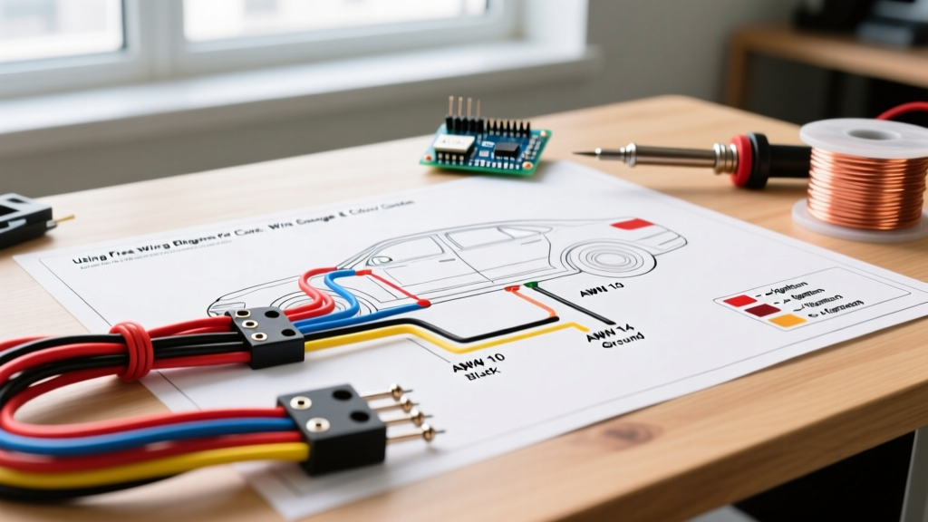

The Hidden Language of Automotive Wiring Diagrams
Finding free wiring diagrams for cars on enthusiast forums or open-source repair databases is only the first step in a successful electrical modification or repair. While these diagrams excel at showing circuit topology, relay logic, and pinouts, they almost universally fail to provide the two most critical pieces of information for physical execution: wire gauge (AWG/mm²) and standardized color codes. As vehicles in 2026 increasingly integrate 48V mild-hybrid systems and complex CAN-FD networks, guessing wire sizes based on a schematic line thickness is a fast track to voltage drop, melted insulation, or catastrophic module failure.
This guide bridges the gap between digital schematics and physical wiring, providing the exact gauge matrices, insulation types, and color standards required to safely execute the repairs outlined in your free automotive wiring diagrams.
Automotive Wire Gauge: AWG vs. Metric (mm²)
Unlike household wiring governed strictly by the National Fire Protection Association (NFPA) and the NEC, automotive wiring is governed by SAE International standards (specifically SAE J1128). European diagrams often use metric cross-sectional area (mm²), while American and Japanese diagrams use American Wire Gauge (AWG). Confusing the two is a common edge case that leads to undersized wiring.
Furthermore, automotive wire is not rated the same as building wire. The ambient temperature in an engine bay can exceed 125°C (257°F), which severely derates the ampacity of copper conductors. You must use high-temperature automotive insulation types like GXL (General purpose, thin wall), TXL (Extra thin wall, high temp), or SXL (Specialty, high temp). Standard PVC THHN wire will melt and short out against the chassis.
SAE J1128 Ampacity & Sizing Matrix (12V Systems)
Use this reference table when translating a free wiring diagram into a physical harness. Ampacity ratings assume a 12V nominal system with a maximum allowable voltage drop of 3% over a standard 10-foot run.
| AWG | Metric (mm²) | Max Amps (Chassis/Cabin) | Max Amps (Engine Bay 125°C) | Common Automotive Application |
|---|---|---|---|---|
| 18 | 0.8 | 6A | 4A | ECU sensors, low-draw LEDs, CAN bus lines |
| 16 | 1.0 | 10A | 7A | Interior lighting, radio memory, tail lights |
| 14 | 1.5 | 15A | 10A | 12V accessory sockets, horn, wiper motors |
| 12 | 2.0 | 20A | 15A | Fuel pump, power windows, seat heaters |
| 10 | 3.0 | 30A | 20A | Headlight relays, ABS modules, cooling fans |
| 8 | 5.0 | 50A | 35A | Starter relay feeds, main distribution blocks |
| 4 | 20.0 | 120A | 85A | Alternator main output, EV 12V battery feeds |
Expert Insight: If your free wiring diagram shows a circuit protected by a 20A fuse, do not automatically use 12 AWG wire if the run exceeds 15 feet. Voltage drop dictates that you must step up to 10 AWG to ensure the load receives adequate voltage, even though the 12 AWG wire can technically handle the thermal load of 20A.
Decoding Automotive Wire Color Standards
One of the most frustrating aspects of using free wiring diagrams for cars is the lack of color standardization across manufacturers. A wire labeled "RD/BK" (Red with Black tracer) on a Ford diagram means something entirely different than on a BMW schematic. However, understanding the baseline standards helps you trace circuits when the physical wire colors have faded or been altered by previous owners.
The SAE / DIN Baseline Color Codes
While OEMs have proprietary palettes, most aftermarket harness manufacturers and general Molex Automotive connector pinouts adhere to a variation of SAE and DIN 72551 color abbreviations:
- BK (Black): Ground (Chassis earth)
- RD (Red): Unswitched Battery Power (B+)
- WT (White): Switched Power (Ignition ON) or Data Lines
- GN (Green): Sensors, Senders, or Right-side lighting
- BU (Blue): Left-side lighting, or 48V mild-hybrid signaling
- YE (Yellow): Airbag systems (SRS) - Never probe these with a standard multimeter.
- OG (Orange): High Voltage (EV/Battery) or CAN-High data
- VT (Violet/Purple): CAN-Low data or specific ECU triggers
OEM Tracer Patterns (The Edge Case)
Modern vehicles use base colors with spiral tracers to denote specific sub-circuits. For example, in General Motors (GM) wiring, a Light Green (LG) wire with a Black (BK) tracer is universally used for the fuel pump relay control. If your free diagram simply says "Fuel Pump Control" without specifying the color, knowing the OEM tracer pattern saves hours of diagnostic time with a multimeter.
Step-by-Step: Tracing a Circuit Using Free Diagrams
When you download a schematic from an open-source database, follow this exact diagnostic flow to verify the physical harness matches the digital diagram.
- Identify the Power Source and Ground Topology: Locate the specific fuse and ground splice pack (e.g., GM's G200 or Ford's G101) on the diagram. Do not assume a generic chassis ground.
- Back-Probe, Don't Pierce: Use a dedicated T-pin back-probe kit (approx. $15-$20) to test connectors. Piercing wire insulation with a standard multimeter probe introduces moisture, leading to green rot (copper oxidation) inside the insulation jacket within 6 to 12 months.
- Verify Voltage Drop, Not Just Continuity: A wire with a single strand of copper intact will show continuity (0.0 ohms) on a cheap meter but will fail under load. Use a True-RMS multimeter like the Fluke 87V MAX ($450+) or a Power Probe IV ($280) to measure voltage drop across the circuit while it is under active load. A drop greater than 0.2V on the ground side indicates high resistance.
- Map the Tracers: Use a magnifying loupe to identify the spiral tracer color on the physical wire and match it against the diagram's alphanumeric code (e.g., OG/BK).
Advanced Edge Cases: CAN Bus and 2026 EV Systems
As automotive architecture evolves, the rules for interpreting wiring diagrams have shifted drastically. If you are working on a vehicle manufactured in the last five years, you will encounter high-speed data networks and high-voltage systems that require specialized handling.
CAN Bus Wiring Rules
Controller Area Network (CAN) diagrams in free resources often look like simple parallel lines. In reality, CAN-High and CAN-Low must be routed as a twisted pair (typically 1 twist per inch) to cancel out electromagnetic interference (EMI). They are terminated with a 60-ohm resistor network. If your diagram shows a CAN bus line, you must use unshielded twisted pair (UTP) automotive wire; running them parallel or using coaxial cable will result in bus-off errors and module communication failures.
48V Mild-Hybrid and Full BEV High Voltage
In 2026, 48V mild-hybrid systems are ubiquitous. Wiring diagrams for these systems often use Blue or Yellow sheathing to denote the 48V architecture, separating it from standard 12V red/black wiring. For full Battery Electric Vehicles (BEVs), ISO 6722 strictly mandates that all high-voltage cables (typically 400V to 800V) be shielded and colored Orange. Never attempt to repair or modify orange cabling based on a free internet diagram; these systems require manufacturer-certified high-voltage training and insulated tooling to prevent lethal arc flashes.
Crimp vs. Solder: The Automotive Reality
A final, critical note when executing repairs based on free wiring diagrams: Do not solder automotive wire splices. While soldering is common in household electronics and static DIY projects, the constant vibration and thermal cycling of a vehicle chassis will cause solder to wick under the wire insulation. This creates a rigid, brittle point that will inevitably snap due to vibration fatigue. OEMs and professional harness builders exclusively use open-barrel crimps or adhesive-lined heat shrink butt splices (such as 3M Highland or Molex equivalents). The adhesive melts and seals the splice from moisture, while the crimp maintains a gas-tight, flexible mechanical bond.
By combining the logical roadmap of free wiring diagrams with the physical realities of AWG sizing, temperature derating, and OEM color standards, you can safely and reliably modify or repair any automotive electrical system.