
Why Dual Fans Require Dedicated Relay Circuits
Upgrading from a mechanical clutch fan to a dual electric fan setup is one of the most effective modifications for freeing up parasitic horsepower and improving low-speed cooling in heavy-tow vehicles or LS-swapped platforms. However, high-CFM dual fan assemblies—such as the popular Ford Mark VIII or aftermarket SPAL units—draw massive current. A single high-performance fan can pull 25 to 35 amps on startup, meaning a dual setup can demand over 60 amps continuously.
Running this kind of amperage through a factory thermostat switch, a cheap dashboard toggle, or an under-gauged harness is a guaranteed recipe for melted insulation and electrical fires. This is where a properly executed dual electric fan relay wiring diagram becomes critical. By using heavy-duty relays as remote-controlled switches, you isolate the high-current power circuit from the low-current control circuit, ensuring your thermal switches and wiring remain safe and reliable for years.
The Hidden Danger: Alternator Idle Output and Staggered Triggering
Before cutting a single wire, you must understand the relationship between your alternator's idle output and dual fan startup. Many enthusiasts wire both fans to trigger simultaneously at a single temperature threshold (e.g., 205°F). When both fans kick on at the exact same millisecond, the instantaneous current spike can exceed 70 amps.
Expert Insight: A standard 105-amp alternator only produces about 60% to 70% of its rated output at idle RPM. If your dual fans pull 70 amps while the engine is idling at a stoplight, system voltage will plummet below 11.5V. This voltage drop can starve your EFI system, cause ignition misfires, and reset your ECU.
The solution is staggered triggering. By wiring the relays to a dual-stage thermal controller, Fan 1 activates at 195°F and Fan 2 activates only if the temperature climbs to 210°F. This halves the instantaneous electrical load and keeps your charging system stable.
Bill of Materials: Exact Specs for a Bulletproof Setup
Do not compromise on materials when dealing with 60+ amp circuits under the hood. Use the following specifications to ensure longevity and safety:
| Component | Specification / Part Number | Purpose |
|---|---|---|
| Relays | Bosch 0332014150 (40A SPDT) or Tyco V23134 (Diode Suppressed) | High-current switching |
| Power Wire | 10 AWG GXL or SXL (Cross-linked Polyethylene) | Handles 30-40A continuous; rated for 125°C under-hood heat |
| Control Wire | 14 AWG SXL | Low-current relay coil and thermal switch routing |
| Overcurrent Protection | 40A Maxi-Fuse Holders with Bussmann Maxi Fuses | Protects power feed from battery to relay Pin 30 |
| Terminals | Adhesive-Lined Heat Shrink Ring Terminals (10-8 AWG) | Prevents moisture intrusion and corrosion at crimp joints |
| Thermal Controller | Derale 16739 (Dual-Stage) or Dakota Digital PAC-2800BT | Provides staggered grounding signals for the relays |
The 5-Pin Bosch Relay Pinout Matrix
To wire the diagram correctly, you must understand the standard ISO 5-pin automotive relay layout. According to the Littelfuse Automotive Relays Guide, the pin designations are standardized across almost all major manufacturers:
- Pin 30 (Common): High-current 12V input from the battery (via fuse).
- Pin 87 (Normally Open): High-current output to the fan positive wire.
- Pin 87a (Normally Closed): Not used in standard fan setups (leave empty or insulate).
- Pin 86 (Coil Power): Low-current 12V ignition-switched source.
- Pin 85 (Coil Ground): Low-current ground signal from the thermal switch.
Step-by-Step Dual Electric Fan Relay Wiring Diagram Walkthrough
Step 1: High-Current Power and Ground Routing
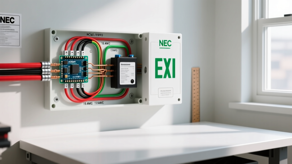
Begin by running your 10 AWG GXL power wire from the positive battery terminal to a centralized relay mounting block. Install a 40A Maxi-Fuse within 8 inches of the battery terminal. This is a non-negotiable safety requirement; if a chafed wire shorts to the chassis, the fuse must blow before the harness catches fire.
From the fuse, split the 10 AWG wire using a sealed, adhesive-lined step-down butt connector to feed Pin 30 on both Relay 1 and Relay 2. Next, run a separate 10 AWG wire from Pin 87 on each relay directly to the positive terminal of its respective cooling fan.
For the fan grounds, do not rely on painted radiator supports. Run 10 AWG ground wires from the fans directly to the engine block or a dedicated chassis grounding bus bar. Use a wire brush to remove all paint and corrosion down to bare metal, and secure the ring terminal using a stainless steel star washer to bite into the metal and prevent vibration loosening.
Step 2: Wiring the Control Circuit (Pins 85 & 86)
The control circuit requires significantly less current, so 14 AWG SXL wire is perfectly adequate. Locate a reliable 12V ignition-switched source in your fuse box (a circuit that only has power when the key is in the 'Run' position). Wire this source to Pin 86 on both relays. This ensures the fans cannot run after you turn the engine off and exit the vehicle, preventing a dead battery.
Next, wire Pin 85 on Relay 1 to the 'Stage 1' output on your dual-stage thermal controller. Wire Pin 85 on Relay 2 to the 'Stage 2' output. The thermal controller's probe should be threaded into your engine block, intake manifold, or a dedicated weld bung on the upper radiator hose.
Step 3: Managing Inductive Kickback (Crucial for PWM Controllers)
If you are using a modern Pulse Width Modulated (PWM) controller like the Dakota Digital PAC-2800BT to ramp fan speeds smoothly, you must address inductive kickback. When a relay coil de-energizes, the collapsing magnetic field generates a reverse voltage spike that can exceed 100V. As detailed in the Texas Instruments Application Note on Relay Drivers, this spike will instantly destroy the sensitive MOSFET transistors inside a PWM controller.
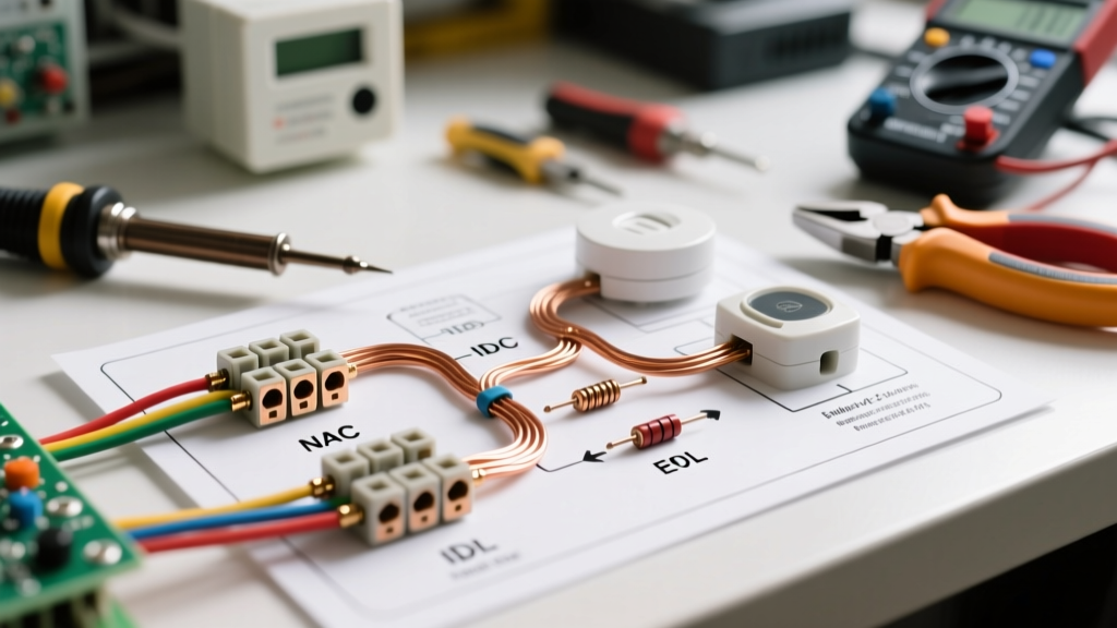
The Fix: You must either purchase relays with internal flyback diodes (such as the Tyco V23134 series) or manually solder a 1N5408 rectifier diode across Pins 85 and 86 on standard relays. The silver stripe on the diode must point toward Pin 86 (the positive side). This creates a safe recirculation loop for the voltage spike, protecting your expensive controller.
Advanced Troubleshooting & Edge Cases
Even with a perfect diagram, real-world variables can cause issues. Here is how to diagnose the most common dual fan electrical failures:
Voltage Drop Testing
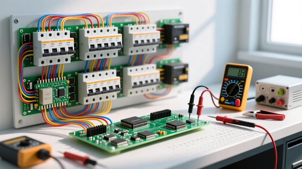
If your fans seem sluggish or cycle on and off rapidly, you likely have a voltage drop. Set your digital multimeter to DC Volts. Place the red probe on the battery positive post and the black probe on the fan's positive terminal while the fans are running. A reading above 0.5V indicates excessive resistance in the power wire, usually due to undersized wire, a corroded Maxi-Fuse holder, or a loose crimp. Repeat the test on the ground side (black probe on battery negative, red probe on fan casing).
Thermal Switch Hysteresis
If your fans are 'short-cycling' (turning on and off every 3 seconds), your thermal switch lacks proper hysteresis or is placed in a turbulent coolant pocket. High-end controllers allow you to program a 'turn-off' threshold that is 10°F to 15°F lower than the 'turn-on' threshold, ensuring the fans run long enough to pull actual heat out of the radiator core before shutting down.
Parasitic Draw from Back-feeding
If you accidentally wire Pin 86 to a constant 12V source instead of an ignition-switched source, and your thermal switch remains closed as the engine cools down, the fans will run until the battery is dead. Always verify your control circuit power source with a test light before making final crimps; the light must turn off when the ignition key is removed.
Summary
Executing a proper dual electric fan relay wiring diagram is about more than just making the fans spin. It requires respecting wire gauge limits, understanding alternator output curves at idle, and protecting solid-state controllers from inductive voltage spikes. By using GXL cross-linked wiring, staggered thermal triggering, and flyback diode suppression, you will build a cooling system electrical harness that is reliable, safe, and capable of handling the most extreme under-hood environments.