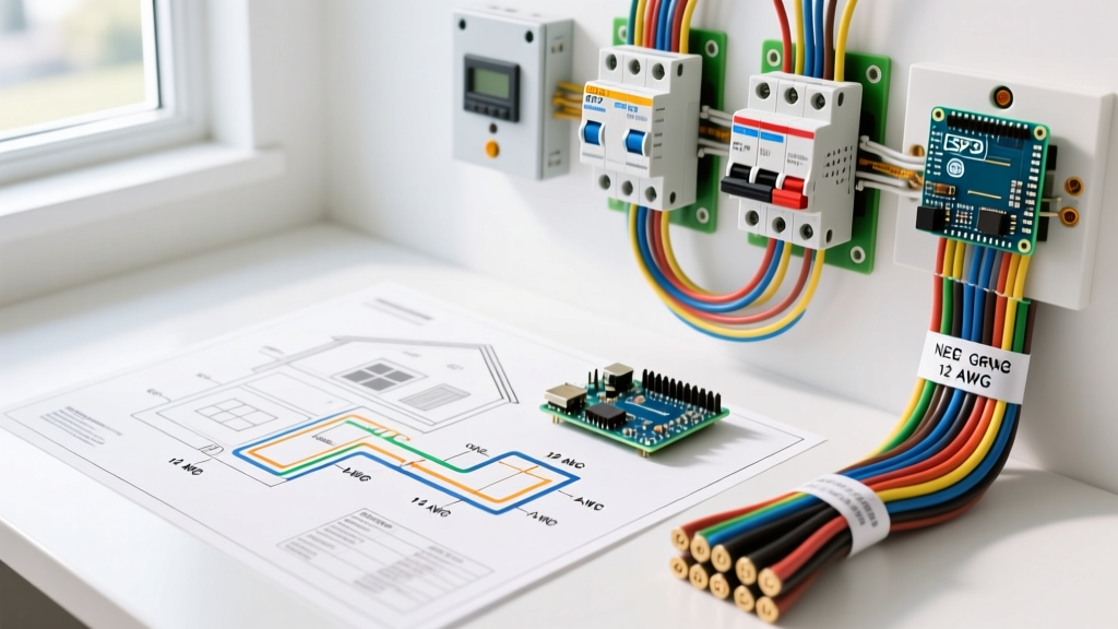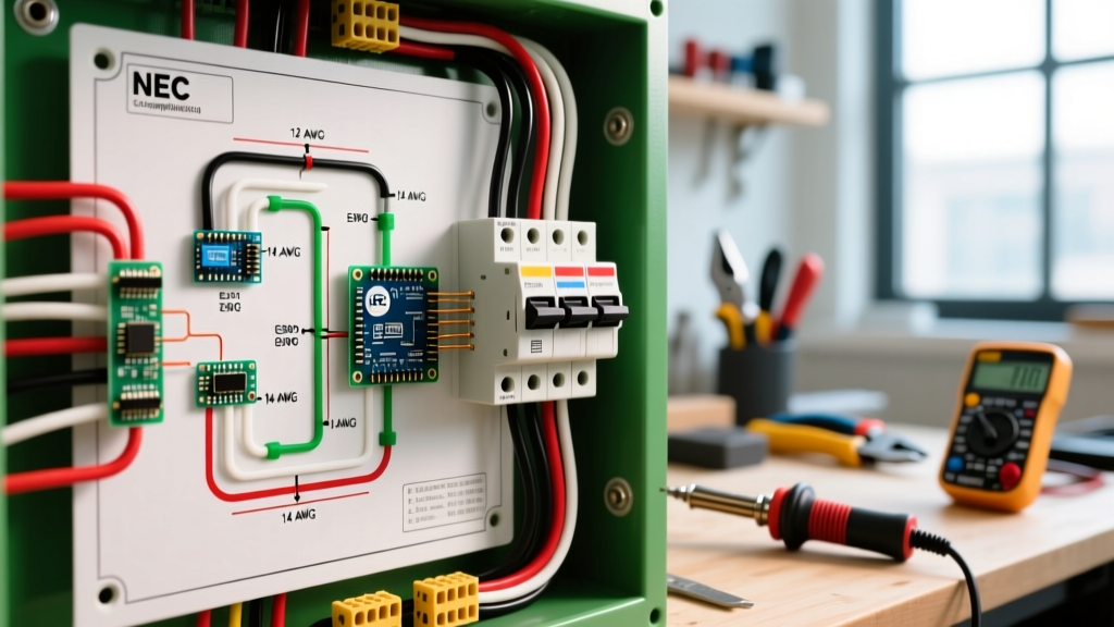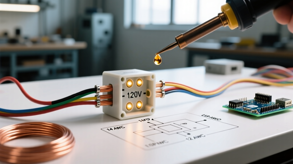

Understanding the Wiring Diagram for Photocell Integrations
When automating exterior appliances, security lighting, and commercial ventilation systems, mastering the wiring diagram for photocell setups is a fundamental skill for any DIY electrician or appliance technician. A photocell (or photoelectric control) acts as an ambient light-activated switch. While most homeowners associate them with simple dusk-to-dawn porch lights, as of 2026, photocells are heavily utilized in advanced appliance wiring—such as triggering 240V exterior exhaust fans, agricultural louvers, and HVAC condenser ancillary lighting via heavy-duty contactors.
This comprehensive tutorial breaks down the exact wiring schematics for both standard 120V direct-load security fixtures and advanced 240V relay-switched appliance integrations. We will cover wire gauge selection, modern LED inrush current challenges, and critical National Electrical Code (NEC) compliance standards.
The Evolution: CdS Cells vs. Solid-State Photodiodes
Historically, photocells relied on Cadmium Sulfide (CdS) photoresistors. These analog components degrade over time when exposed to UV radiation, leading to 'false dawn' failures where the light turns on during the day. Modern 2026-compliant photocontrols, such as the Hubbell PA112 or Intermatic K4221, utilize solid-state photodiodes paired with internal microcontrollers. These microcontrollers provide crucial time-delay circuits (typically 15 to 30 seconds) that prevent rapid short-cycling when car headlights or lightning flashes sweep across the sensor.
Standard 120V Wiring Diagram for Photocell Security Fixtures
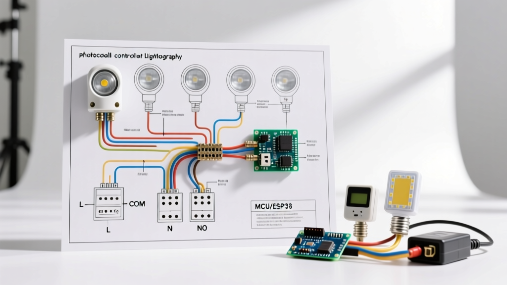
For standard residential security lights (e.g., LED floodlights, wall packs), the photocell is wired directly in series with the hot leg. Most modern photocells are 3-wire systems requiring a neutral connection to power their internal solid-state switching electronics.
Step-by-Step 120V Direct Wiring
- Identify the Wires: Your photocell will have three wires: Black (Line In), Red (Switched Load Out), and White (Neutral).
- Connect the Neutral: Wire the White wire from the photocell directly to the White (neutral) wire of your power supply and the White wire of the light fixture. Use a 3-port Wago connector or a properly sized wire nut.
- Connect the Line In: Wire the Black wire from the photocell to the Black (hot) wire coming from your breaker panel.
- Connect the Load Out: Wire the Red wire from the photocell to the Black (hot) wire of the light fixture.
- Grounding: Bond the bare copper or green ground wires from the supply, the fixture, and the metal junction box together. Note: The photocell itself does not have a ground wire, as it is double-insulated.
CRITICAL SAFETY WARNING: Never switch the neutral wire. If you place the photocell on the neutral leg, the fixture will remain energized at 120V even when the light is off, creating a severe shock hazard during bulb replacement or maintenance. Always switch the hot leg.
Advanced Appliance Integration: 240V Contactor Wiring
Photocells are rarely rated to switch 240V directly. If you need to automate a 240V appliance—such as a heavy-duty exterior exhaust fan, a workshop dust collector, or agricultural ventilation—you must use the photocell to trigger a Definite Purpose Contactor (DPC) or a heavy-duty relay like the Intermatic T104. In this scenario, the photocell operates on a 120V control circuit, while the contactor handles the 240V appliance load.
Wiring the Control Circuit (120V)
You will need to pull a 120V supply from one leg of your split-phase panel (L1) and a neutral.
- Connect 120V Hot (Black) to the Photocell Black.
- Connect 120V Neutral (White) to the Photocell White and one side of the contactor coil (A1).
- Connect the Photocell Red (Switched Hot) to the other side of the contactor coil (A2).
Wiring the Power Circuit (240V)
- Connect your 240V supply (L1 and L2) to the contactor's Line terminals (1 and 3).
- Connect your 240V appliance load wires to the contactor's Load terminals (2 and 4).
- Ensure the appliance ground is bonded directly to the grounding bar, bypassing the contactor.
Wire Gauge & Component Sizing Matrix
Selecting the correct wire gauge and breaker size is critical to prevent voltage drop and thermal failures. Refer to the table below for standard 2026 appliance wiring parameters based on National Fire Protection Association (NFPA) guidelines.
| Load Type | Voltage | Max Amperage | Wire Gauge (Copper) | Breaker Size | Recommended Contactor |
|---|---|---|---|---|---|
| LED Security Lights (Direct) | 120V | 15A | 14 AWG | 15A / 20A | N/A (Direct Switch) |
| Exterior Exhaust Fan | 240V | 20A | 12 AWG | 20A 2-Pole | 30A DP Contactor |
| Workshop Dust Collector | 240V | 30A | 10 AWG | 30A 2-Pole | 40A DP Contactor |
| HVAC Ancillary Lighting | 277V | 20A | 12 AWG | 20A 1-Pole | NEMA Twist-Lock Base |
Real-World Troubleshooting & Edge Cases
Even with a perfect wiring diagram for photocell setups, real-world environments introduce variables that can cause system failures. Here are the most common edge cases encountered by appliance technicians:
1. Contact Welding from LED Inrush Current
Modern commercial LED drivers contain large internal capacitors. When energized, they can draw an inrush current up to 100 times their steady-state rating for a few milliseconds. A standard 15A photocell switching a 500W LED array may experience internal contact welding on the very first night, causing the light to stay on permanently. Solution: Always use a photocell rated for 'High Inrush' (e.g., 1000A ballast rating) or use the contactor method detailed above.
2. False Triggering (Light Bounce)
If a security light turns on and off repeatedly at dusk, the photocell is likely detecting its own light output or light bouncing off a nearby reflective surface (like a white soffit or snow). Solution: Reposition the sensor so it faces the open sky, away from the fixture's beam angle, or upgrade to a model with an adjustable time-delay potentiometer.
3. NEMA Twist-Lock Receptacle Failures
In commercial applications, photocells often plug into an ANSI C136.41 NEMA twist-lock receptacle on top of the fixture. Moisture ingress into these receptacles can cause corrosion on the 3-pin or 5-pin contacts, leading to voltage drops and flickering. Apply a small amount of dielectric grease to the pins during installation to prevent oxidation.
NEC Compliance and Energy Efficiency Standards
When integrating photocells into exterior appliances and lighting, compliance with the National Electrical Code (NEC) is mandatory. According to NEC Article 410, outdoor lighting fixtures and their associated controls must be listed for wet locations if exposed to weather. Furthermore, the U.S. Department of Energy (DOE) strongly recommends photoelectric controls in conjunction with motion sensors to maximize energy efficiency in commercial exterior lighting designs.
For motorized appliances (like exhaust fans) switched via a photocell and contactor, NEC Article 430 dictates that the motor must still have a local, manually operable disconnect switch within sight of the appliance. The photocell acts as an automated controller, not a safety disconnect.
Frequently Asked Questions (FAQ)
Can I wire a photocell to a dimmer switch?
No. Standard photocells are designed for strict ON/OFF binary switching. Placing a dimmer in series with a photocell will starve the photocell's internal microcontroller of the voltage it needs to operate, resulting in erratic behavior or total failure.
Does a photocell consume power when the light is off?
Yes. Solid-state photocells draw a tiny amount of standby current (typically less than 0.5 watts) to keep the internal photodiode and timing circuit active. This is negligible and will not impact your electrical bill.
Why does my 240V appliance hum when the photocell switches it on?
If you hear a loud hum from the contactor, it indicates the coil is receiving insufficient voltage (often due to voltage drop over long wire runs) or the contactor's magnetic armature is obstructed by debris. Verify the control circuit voltage is within 10% of the coil's rated voltage.