
Why Precision Matters in 2026 Ethernet Terminations
As network demands surge in 2026, with multi-gigabit Wi-Fi 7 access points and 2.5GbE/5GbE desktop NICs becoming standard, the physical layer of your network must be flawless. A poorly terminated wall jack is the single most common bottleneck in residential and commercial structured cabling. Understanding the correct wiring diagram for ethernet wall jack installations is no longer just about getting a link light to turn on; it is about preserving the 250 MHz bandwidth of Category 6 (or 500 MHz for Cat6A) and preventing packet loss caused by Near-End Crosstalk (NEXT) and Return Loss.
In this comprehensive walkthrough, we will detail the exact steps to terminate a Cat6 solid-copper cable into a standard 110-style keystone jack. We will cover the T568B standard, precise measurement tolerances, and the specific failure modes that plague DIY installers. Expect to spend roughly $4.50 to $6.00 per high-quality keystone jack (such as the Leviton 6110G-RW6) and around $160 for a 1,000-foot spool of 23 AWG solid copper Cat6 cable (like Southwire's premium line) in today's market.
Essential Tools and Materials
Before examining the wiring diagram, ensure you have the correct professional-grade tools. Using improvised tools often leads to damaged Insulation Displacement Connectors (IDCs) and failed certification tests.
- Cable: 23 AWG Solid Copper Cat6 (Avoid Copper-Clad Aluminum or CCA, which violates NEC fire codes and fractures easily).
- Keystone Jack: Cat6 rated, 110-style IDC termination (e.g., Leviton 6110G-RW6 or TrueCABLE Cat6 RJ45 Toolless Keystone).
- Punch Down Tool: Impact punch down tool with a 110 blade and built-in cutter (e.g., Klein Tools VDV226-110 or an impact tool with a dual-wire 110 blade).
- Stripping Tool: Precision jacket stripper to avoid nicking the copper conductors.
- Tester: Wiremapper and basic certifier (e.g., Fluke Networks IntelliTone Pro 200 or a basic PoE-capable wiremapper).
Decoding the Wiring Diagram: T568A vs. T568B
The Telecommunications Industry Association (TIA) recognizes two primary pinout standards for 8-position modular connectors: T568A and T568B. While both provide identical electrical performance, T568B has become the de facto standard for commercial and residential installations in North America. The most critical rule of structured cabling is consistency: never mix T568A on one end of a link and T568B on the other, as this creates a crossover cable that will prevent modern auto-MDIX switches from establishing a link in certain edge cases.
T568B Pinout Reference Table
When looking at the back of a keystone jack, the manufacturer prints a color-coded wiring diagram. You must follow the 'B' color code. Below is the exact mapping for T568B:
| Pin Number | Wire Color | Pair Number | Function (10/100/1000BASE-T) |
|---|---|---|---|
| 1 | White-Orange | Pair 2 | Transmit + (TX+) |
| 2 | Orange | Pair 2 | Transmit - (TX-) |
| 3 | White-Green | Pair 3 | Receive + (RX+) |
| 4 | Blue | Pair 1 | Unused (PoE / POTS) |
| 5 | White-Blue | Pair 1 | Unused (PoE / POTS) |
| 6 | Green | Pair 3 | Receive - (RX-) |
| 7 | White-Brown | Pair 4 | Unused (PoE / POTS) |
| 8 | Brown | Pair 4 | Unused (PoE / POTS) |
Step-by-Step Wiring Walkthrough
Follow these precise steps to ensure your termination meets ANSI/TIA-568.2-D performance requirements. According to BICSI Standards and Best Practices, the physical manipulation of the twisted pairs dictates the high-frequency performance of the link.
Step 1: Cable Preparation and Stripping
Measure exactly 1.5 to 2.0 inches from the end of the cable and score the outer PVC jacket using your precision stripper. Rotate the tool around the cable and pull the jacket off. Crucial Edge Case: Inspect the exposed copper wires immediately. If your stripper nicked or scored the copper conductor of any wire, cut the entire section off and start over. A nicked 23 AWG wire will easily snap when punched down or when subjected to the thermal expansion of Power over Ethernet (PoE) loads.
Step 2: Untwisting and Pair Management
Locate the center spline (the plastic cross-divider inside Cat6 cable) and trim it flush with the jacket edge. Now, separate the four twisted pairs. Untwist the pairs only as far down as absolutely necessary to reach the IDC slots on the keystone jack. The Golden Rule: Do not untwist more than 0.5 inches (13mm) of the pair from the point of termination. Untwisting further destroys the balanced geometry of the pair, leading to massive Near-End Crosstalk (NEXT) failures at frequencies above 100 MHz.
Step 3: Seating Wires into the IDC Terminals
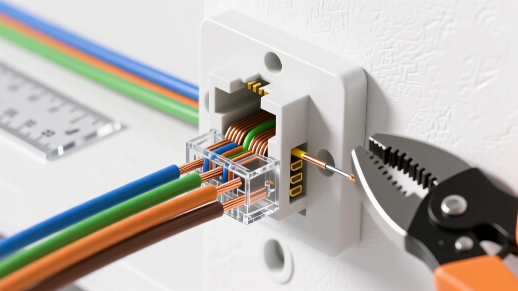
Referencing the T568B wiring diagram printed on your specific keystone jack, map the wires to the correct slots. Note that keystone jacks often route the pairs in a specific physical layout to maintain internal crosstalk isolation. For example, the Blue pair (Pins 4 and 5) is usually seated in the center, while the Orange and Green pairs are split to the outer edges. Gently press the wires into the top of the IDC slots using your fingertips. Do not force them down to the base yet.
Step 4: Punching Down and Trimming
Take your impact punch down tool with the 110 blade. Ensure the 'CUT' side of the blade is facing the outside of the keystone jack. Position the blade directly over the wire and the metal IDC fork. Press down firmly until the tool impacts. This single action seats the wire deep into the fork (creating a gas-tight cold weld) and shears off the excess wire flush with the jack. Repeat for all eight wires. If your tool lacks a cutter, use flush-cut diagonal pliers to trim the excess wire exactly at the edge of the jack body; leaving 'pigtail' stubs acts as an antenna for EMI interference.
Step 5: Wall Plate Assembly and Final Testing
Snap the terminated keystone jack into the wall plate or patch panel housing. Before screwing the faceplate to the drywall, test the link. Use a wiremapper at the patch panel end and the wall jack end. Verify that all 8 pins show continuity and that there are no shorts. For a professional 2026 installation, follow the testing protocols outlined in the Klein Tools Network Data Catalog to ensure your tester supports PoE load testing, verifying that the termination won't overheat when driving 30W (PoE+) or 60W (PoE++) devices like Wi-Fi 7 access points.
Common Failure Modes and Edge Cases
Even with the correct wiring diagram, physical installation errors can ruin a link. Watch out for these specific failure modes:
- Split Pairs: This occurs when an installer maps the pins sequentially by color rather than following the T568B diagram (e.g., putting White-Green on Pin 4 and Blue on Pin 3). The wiremap tester will show 'Pass' for continuity, but the network will fail at gigabit speeds because the transmit and receive signals are no longer traveling on a physically twisted pair, destroying noise cancellation.
- Excessive Bend Radius: Once the cable is pushed back into the wall cavity, ensure it is not bent at a sharp 90-degree angle against the drywall. The minimum bend radius for Cat6 is four times the cable diameter (approximately 1 inch). Kinking the cable alters the internal spacing of the pairs, causing Return Loss failures.
- Debris in IDC Slots: If working in a dusty construction environment, ensure no drywall dust or insulation fibers are trapped inside the IDC forks. This prevents the gas-tight connection, leading to intermittent link drops.
Expert Insight: Never use a flathead screwdriver to push wires into a 110-style keystone jack. A screwdriver will spread the metal tines of the IDC fork, permanently ruining the tension required to bite through the wire's insulation. Always use a proper 110 punch down tool to ensure a reliable, code-compliant termination.
Conclusion
Mastering the wiring diagram for an ethernet wall jack requires more than just memorizing color codes; it demands strict adherence to physical tolerances, proper tool usage, and an understanding of high-frequency signal behavior. By following this T568B step-by-step walkthrough, maintaining the 0.5-inch untwist limit, and utilizing impact termination tools, you guarantee a physical layer capable of supporting the multi-gigabit and high-wattage PoE demands of modern 2026 network infrastructure.