
Introduction to Electric Heat Strip Safety & NEC Compliance
Electric heat strips (also known as auxiliary or emergency heat) are high-wattage resistance heating elements installed inside residential and commercial air handlers. While they provide reliable supplemental heat during extreme cold snaps, they draw massive electrical currents. A standard 15kW heat strip operating at 240V pulls over 62 amps continuously. If the wiring diagram for heat strips is misinterpreted, or if conductors and overcurrent protection are undersized, the result can be catastrophic: melted insulation, arcing faults, or structural fires.
This guide breaks down the critical safety protocols, National Electrical Code (NEC) requirements, and precise wiring sequences necessary to install and troubleshoot electric heat strips safely. Whether you are wiring a 5kW supplemental kit or a massive 20kW whole-home electric furnace, strict adherence to code and manufacturer specifications is non-negotiable.
CRITICAL SAFETY WARNING: Heat strip circuits operate at lethal voltages (208V/240V) and high amperages. Always perform Lockout/Tagout (LOTO) procedures at the main service panel and the local air handler disconnect. Verify zero voltage using a CAT III or CAT IV multimeter before touching any terminals. Never rely solely on a thermostat being in the 'off' position to de-energize the unit.
Core Components of a Heat Strip Wiring Diagram
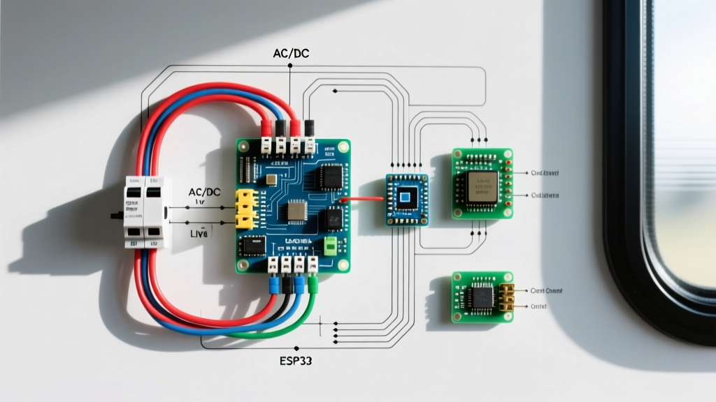
Before making any connections, you must understand the anatomy of a heat strip assembly. A proper wiring diagram for heat strips separates the high-voltage power circuit from the low-voltage control circuit.
- Heating Elements: Nichrome or similar resistance wire coils, typically rated in 5kW increments (e.g., three 5kW coils for a 15kW total package).
- Sequencers (Time-Delay Relays): These devices stage the activation of the heating elements. By delaying the engagement of each coil by 5 to 15 seconds, sequencers prevent massive voltage drops that could stall the blower motor or dim household lighting.
- Thermal Limit Switches: Safety devices wired in series with the elements. Auto-reset limits trip if airflow is restricted, while manual-reset fusible links permanently break the circuit in the event of a catastrophic overheat.
- 24V Control Transformer: Steps down line voltage to power the thermostat and sequencer coils.
NEC Code Requirements for Heat Strip Circuits
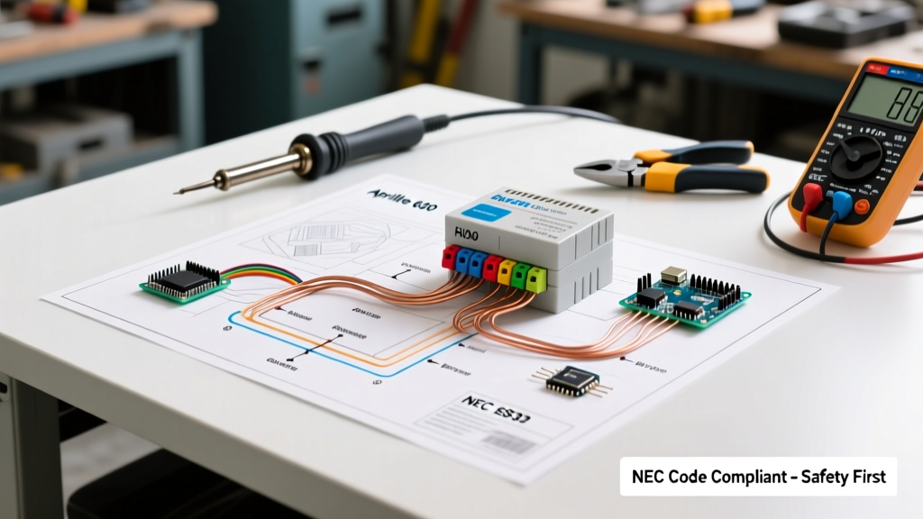
The installation of fixed electric heating equipment is governed primarily by NFPA 70 (National Electrical Code), Article 424. Understanding the 125% continuous load rule is the most vital aspect of sizing your wiring diagram for heat strips.
Article 424 and the 125% Rule
Because electric resistance heating runs for three hours or more, the NEC classifies it as a continuous load. According to NEC 210.20(A) and 424.4(B), the branch-circuit conductors and the overcurrent protective device (breaker) must be sized at no less than 125% of the total connected load.
Example Calculation for a 15kW Heat Strip at 240V:
- Base Amperage: 15,000W / 240V = 62.5 Amps.
- 125% Sizing: 62.5A x 1.25 = 78.125 Amps.
- Conductor Sizing: Requires wire rated for at least 78.1A. Based on the 75°C column of NEC Table 310.16, #4 AWG Copper (rated 85A) is the minimum legal size.
- Breaker Sizing: The next standard breaker size (NEC 240.6) above 78.1A is 80 Amps.
Wire Gauge, Breaker Size, and Max Wattage Matrix
Use the following matrix as a baseline for single-phase, 240V residential heat strip installations. Always verify against the specific air handler manufacturer's data plate.
| Total kW Rating | Base Amps (240V) | 125% NEC Amps | Min. Copper Wire (75°C) | Standard Breaker Size |
|---|---|---|---|---|
| 5 kW | 20.8 A | 26.0 A | #10 AWG | 30 A |
| 8 kW | 33.3 A | 41.6 A | #8 AWG | 45 A or 50 A |
| 10 kW | 41.6 A | 52.0 A | #6 AWG | 60 A |
| 15 kW | 62.5 A | 78.1 A | #4 AWG | 80 A |
| 20 kW | 83.3 A | 104.1 A | #2 AWG | 110 A |
Note: For 208V commercial systems, amperage increases significantly. A 15kW unit at 208V draws 72.1A base, requiring 90.1A wire capacity (#3 AWG) and a 100A breaker.
Step-by-Step Wiring Sequence for a Standard 15kW Heat Strip
Follow this sequence to ensure a safe, code-compliant installation. For deeper insights into energy consumption and efficiency, refer to the U.S. Department of Energy's guide on electric resistance heating.
Phase 1: High-Voltage Power Landing
- Pull Conductors: Run #4 AWG THHN/THWN-2 conductors (H1, H2) and an appropriately sized equipment grounding conductor (EGC) through EMT conduit from the 80A double-pole breaker to the air handler.
- Land the Ground: Terminate the EGC to the air handler's dedicated ground lug. Never land the ground on the neutral bar in a sub-panel or air handler.
- Terminate H1 and H2: Connect the hot legs to the main power terminal block. Crucial Step: Use a calibrated torque screwdriver set to the manufacturer's specification (typically 35 to 45 in-lbs). Loose connections on high-amp heat strips are the #1 cause of terminal melting and fires.
Phase 2: Sequencer and Element Wiring
- Route H1 through the first sequencer's main contacts to the first 5kW element.
- Daisy-chain H1 through the subsequent sequencers to the remaining elements.
- Connect the return side of all heating elements to H2 (the common hot leg).
- Ensure the thermal limit switches are wired in series with the element return path or the sequencer coils, depending on the specific wiring diagram provided by the OEM.
Phase 3: Low-Voltage Control Circuit
- Connect the 24V 'C' (Common) wire from the air handler transformer to the 'C' terminal on the sequencer coils.
- Connect the 'W' (Heat) or 'W2/Aux' wire from the thermostat to the sequencer coil activation terminal.
- Safety Check: Ensure no 240V wires are resting against or sharing the same knockout as the low-voltage thermostat wires without a physical barrier. A short between line voltage and control voltage will instantly destroy the thermostat and transformer.
Common Failure Modes & Code Violations to Avoid
When troubleshooting or inspecting an existing wiring diagram for heat strips, look out for these frequent and dangerous errors:
- Undersized Breakers (Nuisance Tripping): Using a 60A breaker on a 15kW (78.1A required) unit. The breaker will trip constantly during extended cold-weather runs, and the constant thermal cycling will degrade the breaker's internal bimetallic strip.
- Welded Sequencer Contacts: If a sequencer fails, its internal contacts can weld together in the closed position. This causes the heat strip to run continuously, even when the blower is off, leading to tripped manual-reset limits or melted plenums. Always replace sequencers in sets.
- Missing Local Disconnect: NEC 424.19 requires a disconnecting means within sight of the heater. If the air handler is in an attic or crawlspace, a local 240V pull-out disconnect or a lockable breaker is mandatory for technician safety.
- Aluminum Wire Oxidation: If using aluminum conductors (e.g., #2 AWG AL for a 15kW unit to save cost), the lugs must be rated CU/AL, and an anti-oxidant compound (like Noalox) must be applied. Failure to do so results in high-resistance joints that overheat over time.
Frequently Asked Questions (FAQ)
Do 240V heat strips require a neutral wire?
No. Pure 240V electric resistance heat strips only require two hot legs (H1, H2) and an equipment ground. However, if your air handler includes a 120V blower motor, control board, or condensate pump, a dedicated neutral wire must be pulled back to the main panel, and the circuit becomes a 4-wire setup (H1, H2, Neutral, Ground).
Can I wire a 15kW heat strip to a standard 100A sub-panel?
It is highly discouraged. A 15kW strip requires an 80A breaker. Running an 80A continuous load on a 100A sub-panel leaves only 20A for all other circuits, violating NEC diversity and continuous load rules. You should upgrade the sub-panel feed to at least 125A or 200A.
Why does my heat strip wiring diagram show two separate breakers?
Larger units (like 20kW or systems with integrated 120V blowers) often require split circuits. One breaker (e.g., 60A) may power the first 10kW of elements, while a second breaker (e.g., 60A) powers the remaining elements and the blower motor. Always follow the OEM schematic on the inside of the air handler blower door.