
Understanding the Electric Fan Relay Wiring Diagram
Wiring an electric fan motor directly to a switch or a low-current microcontroller is a common mistake that leads to melted switches, fried logic boards, and premature motor failure. An electric fan relay wiring diagram solves this by using a low-current control circuit to switch a high-current load circuit. Whether you are building a custom automotive cooling system, a 24V solar ventilation array, or an industrial HVAC exhaust setup, understanding how to properly wire a relay to a fan motor is a foundational electrical skill.
In this comprehensive motor wiring tutorial, we will break down the exact pinouts, wire gauge requirements, and advanced protection mechanisms—like flyback diodes—required to build a reliable, code-compliant fan circuit in 2026.
Why Fan Motors Require Relay Isolation
Electric fan motors are highly inductive loads. According to the NEMA MG-1 Motors and Generators Standard, DC and AC induction motors experience a massive inrush current (often 3 to 6 times the running current) when starting from a dead stop. This is known as Locked Rotor Amperage (LRA).
- Switch Protection: A standard 12V automotive toggle switch rated for 15A will quickly pit and weld its internal contacts if subjected to the 45A inrush spike of a high-CFM cooling fan.
- Microcontroller Isolation: If you are using PWM (Pulse Width Modulation) from an Arduino, ESP32, or a dedicated fan controller, the GPIO pins can only source 20mA to 40mA. A relay coil requires 60mA to 150mA, necessitating a transistor driver and relay isolation.
- Voltage Drop Mitigation: Relays allow you to route the heavy-gauge power wires directly from the battery or power supply to the fan, minimizing voltage drop and ensuring the motor receives full operating voltage.
Standard 5-Pin ISO Relay Pinout Matrix
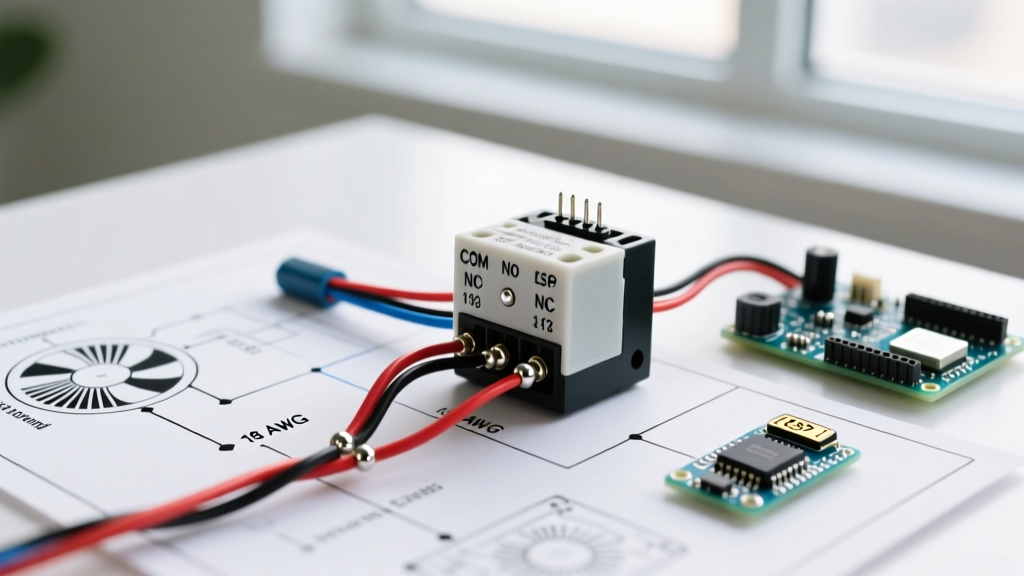
The most common component used in 12V and 24V DC electric fan relay wiring diagrams is the standard 5-pin ISO mini relay (e.g., the ubiquitous Bosch 0332014150 or equivalent Tyco/Eaton models). Below is the universal pinout matrix you must memorize for motor wiring.
| Pin Number | Function | Circuit Type | Wire Color Standard (Typical) |
|---|---|---|---|
| 85 | Coil Ground | Control (Low Current) | Black |
| 86 | Coil Power (+12V/24V) | Control (Low Current) | Red / White |
| 30 | Common (Power In) | Load (High Current) | Heavy Red (Battery +) |
| 87 | Normally Open (NO) | Load (High Current) | Heavy Blue / Green (To Fan) |
| 87a | Normally Closed (NC) | Load (High Current) | Not used for standard fans |
Expert Note: For standard electric fan applications, you will only use pins 30 and 87 for the load side. Pin 87a is left completely unconnected and insulated to prevent accidental short circuits against the chassis.
Step-by-Step Wiring Procedure for 12V/24V DC Fans
Follow this exact sequence to wire your relay. This guide assumes a 12V DC system, but the topology applies equally to 24V DC systems provided you use a 24V coil relay.
Step 1: Wire the High-Current Load Circuit
- Run a heavy-gauge wire (see sizing table below) from the positive terminal of your battery or power supply to an inline fuse holder. Place the fuse as close to the power source as possible.
- Run the wire from the fuse holder to Pin 30 on the relay.
- Connect a wire from Pin 87 directly to the positive terminal of the electric fan motor.
- Ground the negative terminal of the fan motor directly to the chassis or the negative bus bar using the same heavy-gauge wire.
Step 2: Wire the Low-Current Control Circuit
- Run an 18 AWG or 16 AWG wire from your ignition switch, thermostat, or manual toggle switch to Pin 86.
- Connect Pin 85 to a clean, bare-metal chassis ground or the negative bus bar.
Step 3: Install the Flyback Diode (Critical for Solid-State Switches)
When the relay coil is de-energized, the collapsing magnetic field generates a massive reverse voltage spike (back-EMF). If your control switch is a solid-state device, a transistor, or a microcontroller, this spike will instantly destroy the silicon junction. As detailed in the All About Circuits relay guide, you must install a flyback diode.
- Solder a 1N4007 rectifier diode across Pins 85 and 86.
- Orientation is critical: The silver stripe on the diode (cathode) must face Pin 86 (the positive power side). The unmarked end (anode) must face Pin 85 (ground).
Wire Gauge and Overcurrent Protection Sizing
Undersized wires cause voltage drop, which forces the fan motor to draw more amps to compensate, leading to thermal runaway. Use the following matrix to size your load wires (Pins 30 and 87) based on the fan's maximum running amperage.
| Fan Max Running Amps | Recommended Wire Gauge (AWG) | Inline Fuse Rating | Max Continuous Wattage (12V) |
|---|---|---|---|
| Up to 10A | 14 AWG | 15A | 120W |
| 10A to 20A | 12 AWG | 25A | 240W |
| 20A to 30A | 10 AWG | 35A or 40A | 360W |
| 30A to 50A | 8 AWG | 60A | 600W |
Note: Control circuit wires (Pins 85 and 86) only carry the coil current (typically under 200mA) and can safely be wired with 18 AWG or 16 AWG stranded copper.
Electromechanical vs. Solid-State Relays (2026 Market Update)
While the standard 5-pin electromechanical relay (EMR) remains the cheapest option (typically $4 to $8 per unit), the 2026 market has seen a massive drop in the price of high-amperage DC Solid-State Relays (SSRs). When reviewing Omron Automation Relays and similar catalogs, you will notice SSRs are becoming the preferred choice for high-cycle fan applications.
- Electromechanical (EMR): Best for budget builds and low-cycle applications (e.g., a fan that turns on once and runs for hours). Susceptible to contact welding if subjected to frequent high-inrush starts.
- Solid-State (SSR): Models like the Omron G3NA series or generic 40A DC-DC SSRs (now available for $15 to $25) have no moving parts, zero acoustic click, and are immune to contact arcing. They are highly recommended for PWM-controlled fans or thermostats that cycle the fan on and off every few minutes.
Advanced Troubleshooting: Failure Modes and Edge Cases
If your electric fan relay wiring diagram is assembled but the motor is not behaving correctly, consult this troubleshooting matrix:
1. Relay Clicks, but Fan Does Not Spin
- Diagnosis: Voltage drop on the load side or welded internal contacts failing to pass current.
- Action: Use a multimeter to check voltage at Pin 87 while the relay is engaged. If you read 12V at Pin 30 but only 4V at Pin 87, the relay contacts are pitted and carbon-fouled. Replace the relay.
2. Fan Runs Slowly and Relay Gets Extremely Hot
- Diagnosis: The relay is undersized for the motor's inrush current, causing the contacts to partially weld and increase internal resistance.
- Action: Measure the fan's actual startup current with a clamp meter featuring a peak-hold function. Upgrade to a 40A or 50A relay, or switch to a DC Solid-State Relay.
3. Microcontroller Resets When Fan Turns Off
- Diagnosis: Back-EMF spike from the relay coil is feeding back into the low-voltage control circuit, causing a brownout on the microcontroller's voltage regulator.
- Action: Verify the 1N4007 flyback diode is installed in the correct orientation. If using a mechanical switch instead of a microcontroller, this symptom will manifest as a visible spark across the switch contacts upon shutoff.
4. Fan Runs Continuously Even When Switch is Off
- Diagnosis: The high-current contacts inside the relay have permanently welded together due to a severe inrush current event or a short circuit in the fan motor.
- Action: Disconnect power immediately. Tap the relay casing lightly with a screwdriver handle; if the fan stops, the contacts were lightly welded and just broke free. The relay is now compromised and must be replaced. Investigate the fan motor for internal shorts or seized bearings causing excessive stall current.
By strictly adhering to this electric fan relay wiring diagram and respecting the physical limitations of inductive motor loads, you will build a cooling or ventilation system that operates safely and reliably for years.