
Introduction to E-Bike Electrical Architecture
Building or converting an electric bicycle in 2026 requires far more than simply bolting on a motor and battery. With the proliferation of high-torque mid-drives and smart Battery Management Systems (BMS) utilizing CAN bus communication, understanding the underlying electrical architecture is critical. A proper wiring diagram for electric bike conversions is not just a map of connections; it is a blueprint for thermal management, signal integrity, and waterproofing. Whether you are installing a Bafang BBSHD 1000W mid-drive, a Grin Technologies All-Axle hub motor, or a custom Kelly Controllers setup, meticulous installation planning prevents catastrophic failures like melted phase wires or fried hall sensors.
This guide breaks down the essential components of e-bike wiring, providing actionable specifications for wire gauge selection, connector types, and routing techniques to ensure your build meets modern safety and performance standards.
Deconstructing the Standard Wiring Diagram for Electric Bike Systems
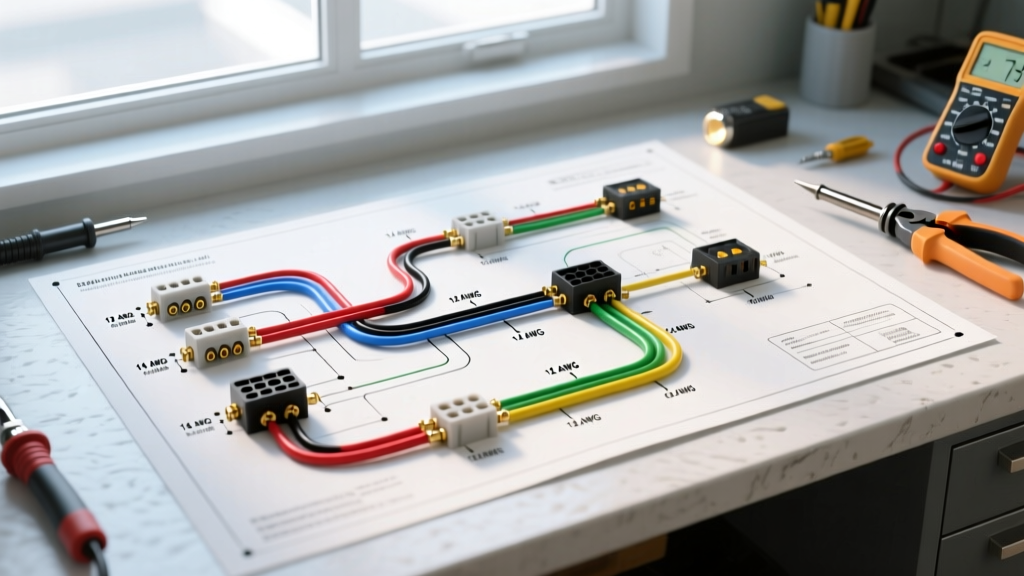
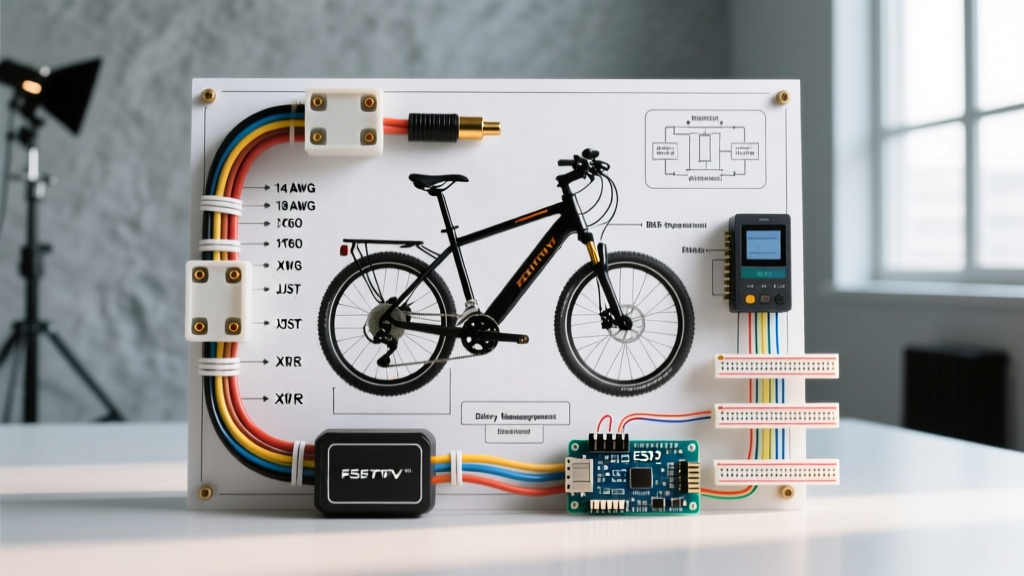
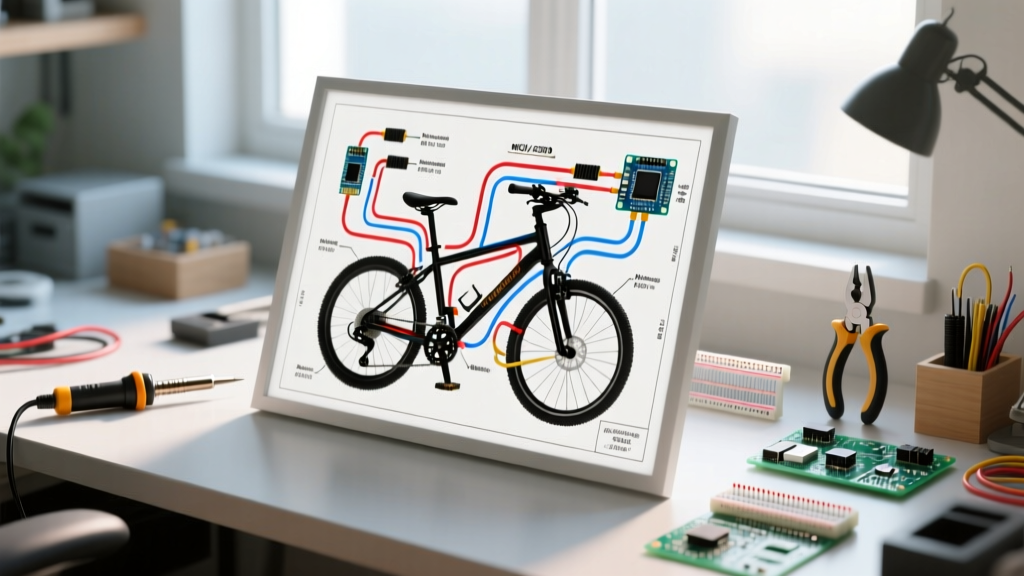
When reviewing your wiring diagram for electric bike builds, you must mentally separate the system into two distinct domains: the high-current power loop and the low-voltage signal loop. Mixing these or routing them improperly leads to electromagnetic interference (EMI) and voltage drops.
The High-Current Power Loop
The power loop carries the raw amperage from the battery pack to the motor controller, and subsequently to the motor phase wires. In a 52V system pulling 40A continuous, you are pushing over 2,000 watts through the main harness.
- Battery to Controller: This is the most critical high-current path. Use high-strand-count silicone wire (minimum 10 AWG for 40A, 8 AWG for 60A+). Always integrate an anti-spark connector, such as the Amass XT90-S, to prevent inrush current from damaging the controller's capacitors upon connection.
- Controller to Motor (Phase Wires): Typically colored Green, Blue, and Yellow. These carry high-frequency, high-current alternating pulses. Use 12 AWG or 10 AWG silicone wire. If extending phase wires, solder joints must be flawless and insulated with 3:1 adhesive-lined marine heat shrink to prevent shorting against the frame.
The Low-Voltage Signal Loop
The signal loop operates between 3.3V and 5V, transmitting data from sensors to the controller. Because these wires carry minimal current, 20 AWG to 24 AWG wire is standard.
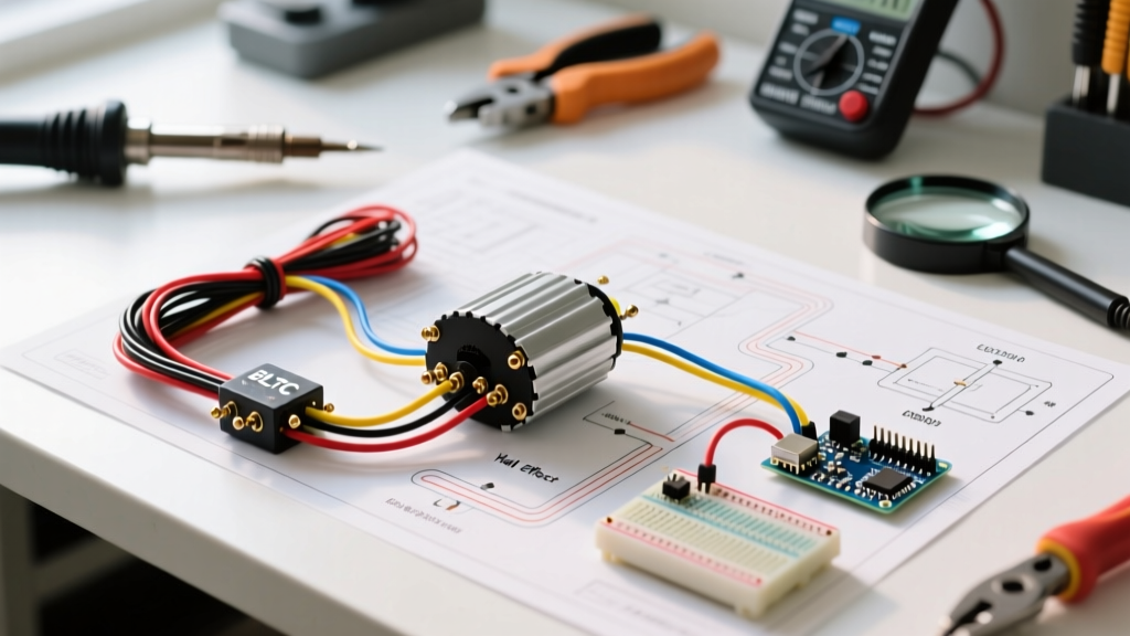
- Hall Sensors: Usually a 5-pin Julet/Higo connector carrying 5V, Ground, and Phase A/B/C signals. Critical Warning: Never swap the 5V and Ground pins when adapting generic wiring diagrams, as this will instantly destroy the motor's internal hall sensors.
- PAS (Pedal Assist Sensor): Typically a 3-pin connector (5V, Ground, Signal). Ensure the magnet disk is spaced exactly 1mm to 3mm from the sensor face for reliable signal pickup.
- Smart BMS Communication: Modern builds often use a UART or CAN bus connection between the BMS (like a JBD or Ant BMS) and the controller to enable real-time thermal throttling and state-of-charge accuracy on the display.
Safety Standard Alert: As of 2026, compliance with UL 2849 is heavily enforced for commercial e-bikes, and DIY builders should adopt these practices. This includes using flame-retardant wire insulation and ensuring all main power connections are housed in rigid, non-conductive enclosures. For more on compliance, refer to the UL E-Bike Safety guidelines.
Wire Gauge (AWG) and Connector Selection Matrix
Selecting the correct wire gauge and connector prevents voltage sag and thermal runaway. The following matrix provides baseline specifications for standard 48V/52V e-bike systems based on continuous current draw.
| System Component | Max Continuous Current | Recommended Wire Gauge | Optimal Connector Type |
|---|---|---|---|
| Battery to Controller (Main) | 30A - 45A | 10 AWG Silicone | Amass XT90 / XT90-S |
| Battery to Controller (High Power) | 50A - 80A | 8 AWG Silicone | Amass QS8 / AS150 |
| Motor Phase Wires | 30A - 60A | 12 AWG - 10 AWG Silicone | 4mm Bullet / 5.5mm Bullet |
| DC-DC Converter Input | 5A - 10A | 16 AWG PVC/Silicone | XT60 / JST-SM |
| Lighting & Accessories | 1A - 3A | 20 AWG PVC | JST-SM / Higo Z204 |
| Hall / PAS / Throttle Signals | < 0.5A | 22 AWG - 24 AWG | Higo/Julet Waterproof (Z206) |
For precise ampacity ratings and voltage drop calculations over longer wire runs (such as on extended cargo bikes), consult the Engineering Toolbox AWG reference charts. Remember that silicone-insulated wire handles heat better than PVC, but its outer diameter is larger, which impacts frame routing.
Step-by-Step Routing and Installation Planning
A flawless wiring diagram for electric bike builds means nothing if the physical installation is compromised by vibration, water ingress, or mechanical wear. Follow this sequence for a professional-grade harness layout.
- Map the Drip Loops: Before securing any cable, ensure every connection point features a 'drip loop'—a downward U-shape in the wire before it enters a connector or enclosure. This prevents rainwater from tracking down the cable directly into the motor or controller seals.
- Apply Dielectric Grease: Apply a small amount of marine-grade dielectric grease to the pins of all low-voltage signal connectors (Higo/Julet) before mating them. This displaces moisture and prevents galvanic corrosion on the tiny 22 AWG pins.
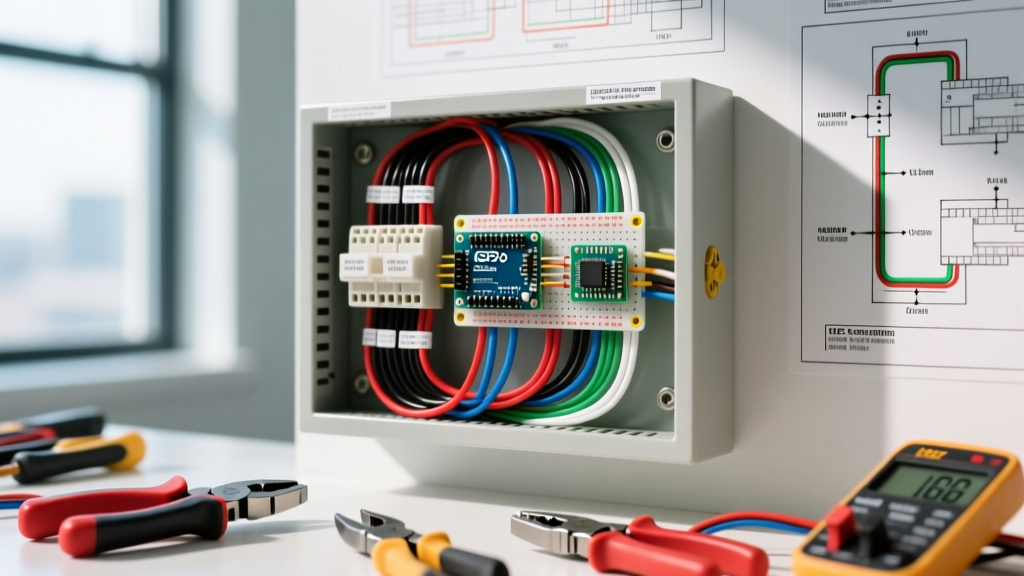
- Isolate the Signal and Power Harnesses: Route the thick battery and phase wires along the down tube and chainstays, while routing the delicate display, throttle, and PAS cables along the top tube or handlebars. If they must cross, do so at a 90-degree angle to minimize EMI.
- Secure with Proper Hardware: Avoid standard zip-ties directly on bare carbon fiber or sharp aluminum edges. Use adhesive-backed cable mounts and wrap wires in split loom tubing or braided PET sleeving. For high-vibration areas near the rear dropout, use stainless steel P-clips with rubber cushions.
- Waterproof the Controller Bay: If your controller is mounted in an external bag or custom frame box, ensure the enclosure has a breathable Gore-Tex vent. Sealed boxes trap condensation caused by temperature swings, leading to internal corrosion.
Common Failure Modes and Edge Cases
Even experienced builders encounter edge cases when adapting generic wiring diagrams to custom frames. Be prepared to troubleshoot these specific failure modes:
- Brake Cutoff Shorts: E-bike brake levers with integrated motor cutoff switches are notorious for failing when wet. If your display throws an Error 08 (brake signal fault), the issue is often water bridging the normally-open (NO) or normally-closed (NC) contacts. Upgrade to sealed hydraulic brake sensors with Higo waterproof connectors.
- Throttle Ghosting: If the motor engages without twisting the throttle, the 5V reference line is likely suffering from voltage sag due to a poor ground connection on the display harness. Check the ground pin at the controller for cold solder joints.
- Phase Wire Melting: This occurs when the bullet connectors between the controller and motor are not fully seated. A 1mm gap inside a 4mm bullet connector creates massive electrical resistance, generating enough heat to melt the silicone insulation and short against the frame. Always tug-test and use a multimeter to verify continuity before applying power.
- PAS Magnet Misalignment: If pedal assist is intermittent, the cadence sensor magnets may be installed backward (wrong polarity) or spaced too far from the sensor. Use a feeler gauge to set the exact 2mm air gap required by most Bafang and Tongsheng mid-drives.
Adhering to Safety and Regulatory Standards
As e-bikes continue to integrate into urban infrastructure, regulatory bodies have tightened safety requirements. The U.S. Consumer Product Safety Commission (CPSC) mandates strict adherence to battery and electrical system safety to prevent fire hazards. When planning your wiring diagram for electric bike projects, always prioritize UL-certified components, especially for the battery pack and charging circuitry.
By treating your e-bike's electrical system with the same rigor as an automotive harness—focusing on correct AWG sizing, waterproofing, and EMI isolation—you ensure a ride that is not only powerful but exceptionally reliable for years to come.