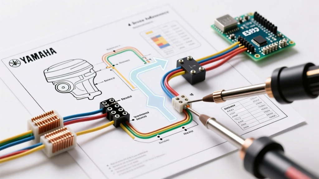

Introduction to Yamaha Marine Electrical Schematics
When troubleshooting marine electrics, locating and correctly interpreting the wiring diagram for Yamaha outboard motor applications is the critical first step. Unlike automotive systems, marine environments demand strict adherence to ABYC (American Boat and Yacht Council) standards, utilizing specialized tinned-copper wiring, sealed connectors, and isolated ground returns to prevent galvanic corrosion. Whether you are diagnosing a no-spark condition on a legacy 2-stroke 150HP V6 or tracing a CANbus communication fault on a 2026 Yamaha XTO Offshore 425HP, the factory schematic is your definitive roadmap.
This reference guide decodes the standard Yamaha outboard wiring diagram, breaking down color codes, subsystem topologies, and actionable diagnostic workflows used by certified marine technicians. We will focus primarily on the ubiquitous Yamaha F-Series 4-stroke platforms (F150, F200, F250), which represent the bulk of the global repower and OEM market.
Standard Yamaha Outboard Wire Color Code Matrix
Yamaha maintains a relatively consistent color-code philosophy across its outboard lineup, though variations exist between legacy analog harnesses and modern digital network cables. Below is the definitive reference matrix for standard analog and power circuits found in the wiring diagram for Yamaha outboard motor engine harnesses.
| Wire Color | Function / Circuit | Voltage / Signal Type | Common Connection Points |
|---|---|---|---|
| Black (B) | Ground / Earth | 0V Reference | Engine Block, Battery Negative, Gauge Ground |
| Red (R) | Battery Positive (B+) | 12V - 14.5V DC | Starter Motor, Main Fuse, Ignition Switch |
| Yellow (Y) | Stator AC Output | 18V - 60V+ AC (Requires DVA) | Stator to Rectifier/Regulator |
| Green (G) | Tachometer Signal | Pulse / AC Ripple | Regulator Output to Tach Gauge |
| Pink (P) | Fuel Sender Signal | Variable Resistance (Ohms) | Fuel Tank Sender to Fuel Gauge |
| White (W) | Engine Stop / Lanyard | Ground to Kill (Closed = Stop) | Kill Switch to CDI / ECM Ground |
| Light Green (LG) | Trim Sender Signal | Variable Resistance | Trim Cylinder Sender to Trim Gauge |
| Brown (Br) | Accessory / Choke (Legacy) | 12V DC (Switched) | Choke Solenoid, Auxiliary Power |
Dissecting the Ignition and Charging Circuits
The core of any Yamaha outboard wiring diagram revolves around the interaction between the stator, the rectifier/regulator, and the engine management computer. Understanding this loop is essential for diagnosing the most common marine electrical failures.
The Stator and Rectifier/Regulator Loop
The stator (alternator) generates raw Alternating Current (AC) as the flywheel's magnetic poles pass over its copper windings. In the wiring diagram, you will see three yellow wires routing from the stator directly into the rectifier/regulator. The regulator converts this AC into Direct Current (DC) to charge the boat's battery and power the ECM (Engine Control Module).
Expert Diagnostic Note: Standard digital multimeters (DMMs) measure RMS (Root Mean Square) voltage, which will display inaccurately low readings when testing a Yamaha stator's raw AC output. Marine technicians must use a DVA (Direct Voltage Adapter) to capture the peak voltage. A healthy Yamaha F150 stator should produce a minimum of 18V AC (DVA reading) at cranking speed, and upwards of 45V AC at 3000 RPM.
ECM vs. CDI: Modern 4-Stroke vs. Legacy 2-Stroke
If your wiring diagram for Yamaha outboard motor applications features a Capacitor Discharge Ignition (CDI) module, you are likely working on a pre-2004 2-stroke or early 4-stroke model. These systems use the stator's high-voltage AC to charge a capacitor, which is then dumped into the ignition coil via a thyristor switch.
Conversely, modern Yamaha F-Series 4-strokes utilize an ECM. The wiring diagram for these models will show a complex network of 5V reference sensors (MAP, TPS, IAT, ECT) feeding the ECM, which then triggers high-impedance fuel injectors and inductive ignition coils using a 12V switched ground. Troubleshooting an ECM circuit requires checking for clean 5V reference signals and verifying that sensor ground loops are not sharing a return path with high-current devices like the fuel pump.
Step-by-Step Diagnostic Workflow Using the Diagram
When faced with a 'cranks but won't start' or 'battery not charging' complaint, follow this structured workflow utilizing the factory schematic. You can source official factory service manuals and parts diagrams through authorized distributors like Yamaha Outboard Parts or specialized marine schematic databases such as Marine Engine.
- Verify the Kill Circuit: Locate the White (engine stop) wire on the diagram. Disconnect the main engine harness at the bullet connector near the starter motor. Use a multimeter in continuity mode to check the White wire against the engine block. If you have continuity with the key in the 'Run' position, your key switch or emergency lanyard is shorting the ignition to ground.
- Test Stator Output (Isolated): Disconnect the three Yellow wires at the rectifier. Set your DMM to AC Volts (with DVA adapter). Crank the engine. Measure Yellow-to-Yellow across all three pairs (1-2, 2-3, 1-3). Readings must be within 10% of each other. A variance indicates a shorted or open stator winding.
- Check Regulator DC Output: Reconnect the stator. Set the DMM to DC Volts. Measure the Red (B+) output wire at the regulator against the engine block while the engine is running at 1500 RPM. You should see between 13.8V and 14.4V. Anything above 15.0V indicates a failed regulator shunt, which will boil the battery and fry the ECM.
- Trace the Fuel Pump Relay: If the engine cranks but the fuel pump doesn't prime, locate the fuel pump relay on the diagram. Check for 12V at the relay coil's power pin when the key is turned to 'ON'. The ECM provides the ground trigger for the relay coil for exactly 3 seconds upon key-on. If power is present but the ground trigger is missing, suspect a faulty crank position sensor (CPS) preventing the ECM from recognizing engine rotation.
Common Failure Modes in Yamaha F-Series Outboards
Based on field service data and technician reports compiled by marine experts at BoatUS, certain electrical failures are endemic to specific Yamaha platforms. Recognizing these edge cases saves hours of diagnostic time.
The 'Key-Off' Battery Drain (F150 / F200 Early Models): A frequent issue on early Yamaha F150 4-strokes involves a failing diode inside the rectifier/regulator (OEM Part # 68V-81910-00-00, retailing around $160). When this diode fails shorted, 12V DC from the battery back-feeds through the Yellow stator wires into the ignition circuit even when the key is off. If a customer reports a dead battery after a week of sitting, but the stator and battery test perfectly, replace the regulator immediately.
Corroded MAP Sensor Grounds: On the F250 and F300 V6 models, the Manifold Absolute Pressure (MAP) sensor shares a 5V ground return with the Intake Air Temperature (IAT) sensor. Because these sensors are located near the top cowling intake, salt spray ingress often corrodes the 3-pin Deutsch connector. The wiring diagram shows this ground routing back to Pin 14 on the ECM. A voltage drop test on this specific ground wire will often reveal a 0.5V to 1.0V drop, causing the ECM to miscalculate air density and trigger a lean-run code, ultimately engaging RPM limitation mode (usually capping the engine at 2000 RPM).
Modern CANbus Networks: The 2026 Perspective
As of 2026, interpreting a wiring diagram for Yamaha outboard motor systems on newer models (such as the Gen II F-Series and XTO Offshore) requires an understanding of digital multiplexing. Traditional analog gauge wiring has been replaced by the Yamaha Command Link and Command Link Plus networks, which operate on a CANbus (Controller Area Network) protocol.
In these schematics, you will no longer see individual wires for tach, speed, or fuel. Instead, you will see a twisted-pair network cable (typically Blue and White wires) routing from the ECM to a central 6Y9 hub, and then out to digital multifunction gauges. Troubleshooting these networks requires an oscilloscope to read the CAN-High and CAN-Low square wave signals, or the use of the proprietary Yamaha Diagnostic System (YDIS) software to ping network nodes and identify dropped packets caused by moisture in the rigging grommet.
Safety and ABYC Compliance
Never substitute standard automotive wire or fuse holders when repairing a Yamaha outboard harness. Marine environments demand UL 1426 tinned marine wire to resist black-wire corrosion (electrolytic degradation). Furthermore, all overcurrent protection devices must be ignition-protected (SAE J1171 / ISO 8846) to prevent sparking in the bilge or engine pan where fuel vapors may accumulate. Always disconnect the battery negative terminal before probing ECM pins or splicing harnesses to prevent accidental shorting of the 5V reference bus, which will instantly destroy the ECM's internal voltage regulator.