
Introduction to Razor Scooter Electrical Architecture
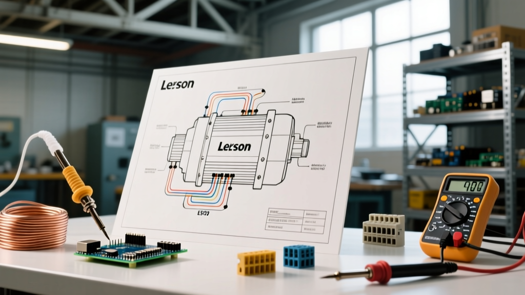
When troubleshooting or modifying personal electric mobility devices, understanding the underlying electrical topology is critical. The wiring diagram for a Razor scooter, specifically the benchmark E300 model, represents a classic 24V brushed DC architecture. While newer 2026 models have introduced brushless hub motors and integrated IoT telemetry to higher-end lines, the E300 and its variants (like the E325 and Sweet Pea) remain the most widely serviced platforms globally. Their reliance on a discrete brushed motor, a standalone PWM (Pulse Width Modulation) controller, and a series-wired Sealed Lead Acid (SLA) battery bank makes them the perfect baseline for learning small-appliance DC wiring.
In this comprehensive guide, we will deconstruct the factory harness, map the controller pinouts, and provide actionable multimeter diagnostics for the most common failure points. Whether you are replacing a burnt-out YK31C-25A controller or upgrading to a modern LiFePO4 battery array, this schematic breakdown will ensure your connections are safe, efficient, and correctly polarized.
The Core Wiring Diagram for a Razor Scooter (E300 Focus)
The electrical system of a stock Razor E300 operates on a nominal 24V DC bus. The power source consists of two 12V 12Ah SLA batteries wired in series to yield 24V (peaking at roughly 29.4V when fully charged off the shelf). The current flows from the battery harness through a 20A inline blade fuse, into the main power switch, and finally into the motor controller. The controller acts as the brain, interpreting analog inputs from the throttle and brake inhibit switches to modulate power to the 250W brushed DC motor.
Expert Safety Note: Always disconnect the main battery harness and engage the physical power switch before probing the controller harness. Capacitors inside the PWM controller can retain a residual charge capable of delivering a sharp shock or shorting out your multimeter if the thick B+ and B- wires touch.
Component Breakdown & Specifications
- Battery Bank: 2x 12V 12Ah SLA (Stock) or 24V LiFePO4 Drop-in (2026 Upgrade Standard)
- Controller Model: YK31C-25A (or equivalent 24V 25A Brushed PWM Controller)
- Motor: 24V 250W Brushed DC (Chain-driven, 550 RPM)
- Throttle: 3-Pin Hall Effect or Potentiometer Twist (0.8V to 3.6V signal range)
- Brake Switch: Normally Closed (NC) inhibit switch integrated into the brake lever
- Main Fuse: 20A ATO Automotive Blade Fuse
Step-by-Step Controller Pinout & Harness Routing
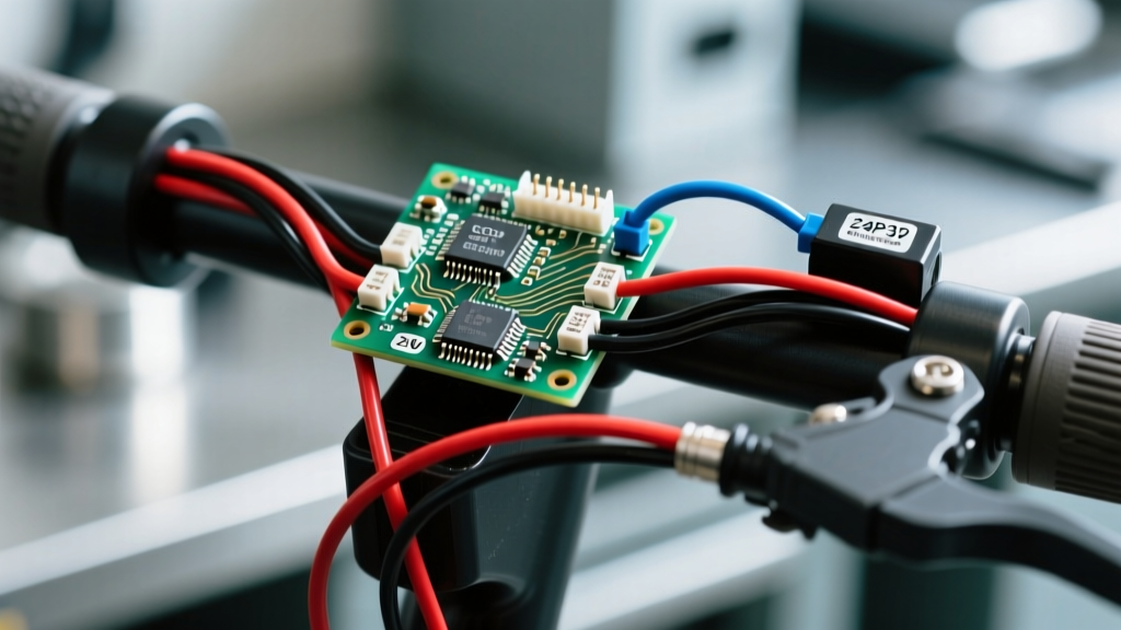
The most complex part of the wiring diagram for a Razor scooter is the controller harness. The YK31C-25A controller uses a mix of heavy-gauge power wires and a multi-pin JST or Molex connector for low-voltage signals. Below is the definitive pinout matrix for the standard 24V Razor controller harness.
| Wire Color / Gauge | Function | Destination / Connection Point | Voltage / Signal Type |
|---|---|---|---|
| Thick Red (14 AWG) | B+ (Battery Positive) | Battery Harness Positive / Main Switch | 24V - 29.4V DC |
| Thick Black (14 AWG) | B- (Battery Negative) | Battery Harness Negative (Common Ground) | 0V DC (Ground) |
| Thick Blue (14 AWG) | M+ (Motor Positive) | DC Motor Positive Terminal | 0V - 24V PWM |
| Thick Yellow (14 AWG) | M- (Motor Negative) | DC Motor Negative Terminal | 0V DC (Ground Return) |
| Thin Red (22 AWG) | Ignition / Lock | Key Switch or Deck Power Button | 24V DC (Switched B+) |
| Thin Red (Harness) | Throttle 5V Supply | Throttle Pin 1 | 5V DC Regulated |
| Thin Black (Harness) | Throttle Ground | Throttle Pin 2 | 0V DC (Logic Ground) |
| Thin Green/White | Throttle Signal | Throttle Pin 3 | 0.8V (Rest) to 3.6V (Full) |
| Thin Grey / 2-Pin | Brake Inhibit | Brake Lever Microswitch | 5V Logic (Pull to GND to stop) |
Throttle Diagnostics: The Most Common Failure Point
If your scooter powers on, the battery voltage reads above 25V, but the motor refuses to engage, the throttle is the primary suspect. The twist throttle on a Razor E300 utilizes a linear Hall-effect sensor. Over time, moisture ingress or physical wear degrades the internal magnets or the sensor IC itself.
How to Test the Throttle Signal with a Multimeter
- Set your digital multimeter to DC Voltage (20V scale).
- Turn the scooter power ON to energize the controller's 5V logic regulator.
- Locate the 3-pin throttle connector near the handlebars.
- Back-probe the connector: Place the black multimeter lead on the Thin Black (Ground) wire, and the red lead on the Thin Green/White (Signal) wire.
- With the throttle fully released, you should read 0.8V to 1.0V.
- Slowly twist the throttle to maximum. The voltage should smoothly climb to 3.4V - 3.6V.
Failure Modes: If the signal wire reads a constant 5V regardless of throttle position, the internal Hall sensor has shorted. If it reads 0V, the 5V supply wire from the controller is severed. According to the Razor Official Support Manuals, replacing the throttle assembly is the standard remedy, as internal sensor repair is rarely cost-effective.
Wire Gauge Sizing and Harness Upgrades
A frequent oversight when repairing the wiring diagram for a Razor scooter is reusing the stock 14 AWG battery wires. While 14 AWG is technically rated for the 20A continuous draw of the E300, the stock wiring uses cheap PVC insulation that becomes brittle over time. Furthermore, voltage sag during hill climbs can cause the controller's Low Voltage Cutoff (LVC) to trigger prematurely.
Upgrading the battery-to-controller harness to 12 AWG silicone-stranded wire reduces resistance, mitigates voltage sag, and handles the 25A peak bursts the YK31C-25A controller can output during startup. Always adhere to standard DC ampacity guidelines, referencing resources like the National Fire Protection Association (NFPA) NEC Standards for chassis wiring limits.
2026 Battery Upgrade Guide: SLA vs. LiFePO4
In 2026, the most popular modification for the Razor E300 is swapping the heavy, voltage-sagging SLA batteries for a 24V (8-Cell Series) Lithium Iron Phosphate (LiFePO4) pack. This upgrade cuts 12 lbs of weight from the deck and doubles the usable range. However, the wiring diagram requires slight modifications to accommodate the new chemistry.
Charging Profile Differences
Stock Razor SLA chargers output roughly 29.4V at 1.5A, utilizing an absorption phase that is incompatible with lithium BMS (Battery Management System) logic. As detailed by Battery University's charging guides, applying an SLA absorption voltage to a lithium pack can confuse the BMS, causing it to trip into protection mode or degrade the cells. You must wire in a dedicated 29.2V LiFePO4 smart charger via a separate DC barrel jack mounted on the deck, bypassing the stock SLA charging port entirely.
Low Voltage Cutoff (LVC) Compatibility
The stock Razor controller has an LVC set at approximately 21V. An 8S LiFePO4 pack has a nominal voltage of 25.6V and a hard cutoff of 20V. This aligns perfectly with the stock controller, meaning you do not need to rewire the LVC sense wires. The controller will naturally cut power before the lithium BMS triggers its own low-voltage protection, preserving the lifespan of your expensive battery upgrade.
Troubleshooting Matrix: Motor and Controller Faults
When the wiring diagram for a Razor scooter is verified but the scooter still fails to operate, use this diagnostic matrix to isolate the faulty component.
| Symptom | Probable Cause | Diagnostic Test & Solution |
|---|---|---|
| Motor stutters or pulses under load | Failing MOSFET in controller or loose motor brush | Check M+ and M- for continuity. Inspect motor carbon brushes for dust buildup. Replace controller if MOSFETs are shorted. |
| Scooter moves with throttle released | Throttle signal wire shorting to 5V wire | Inspect handlebar wiring harness for pinched insulation. Separate and heat-shrink the 5V and Signal wires. |
| Motor spins freely when off, locks when on | Brake inhibit switch stuck in 'engaged' state | Bypass the 2-pin brake switch connector with a jumper wire. If motor runs, replace the brake lever microswitch. |
| Blown 20A Fuse immediately upon power-up | Dead short in B+ wiring or seized motor | Disconnect motor. Replace fuse and turn on. If fuse holds, motor is seized or has an internal winding short. |
Final Safety and Compliance Notes
Working with 24V DC systems may not carry the electrocution risk of AC mains wiring, but the high amperage (up to 40A peak in modified setups) presents a severe fire hazard if connections are poorly crimped. Never use twist-connectors or electrical tape for battery-to-controller joints. Always use adhesive-lined marine heat shrink over properly crimped ring terminals. Furthermore, ensure the inline 20A fuse is located within 6 inches of the battery positive terminal to protect the entire harness in the event of a catastrophic short circuit against the steel deck.
By strictly following this wiring diagram for a Razor scooter and utilizing modern diagnostic techniques, you can reliably restore, maintain, and upgrade these iconic electric vehicles for years of safe operation.