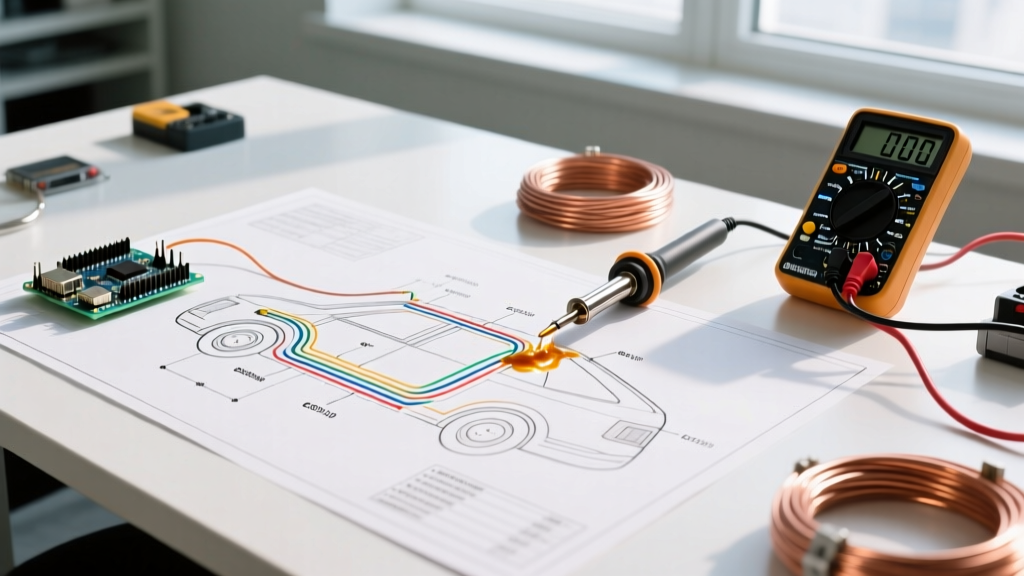

Decoding Vehicle Electrical Systems: A Blueprint for Success
Whether you are troubleshooting a parasitic battery drain on a 2024 Ford F-150, installing a lithium solar bank in a Sprinter camper van, or rewiring a 48V Club Car golf cart, relying on guesswork will inevitably lead to melted harnesses or blown control modules. Modern vehicles are no longer simple mechanical machines; they are rolling networks of CAN bus data lines, pulse-width modulated (PWM) power feeds, and sensitive microcontrollers. To diagnose or modify these systems safely, you must understand the different types of electrical wiring diagrams provided by manufacturers and aftermarket specialists.
This vehicle-specific guide breaks down the four primary diagram formats used in automotive, RV, and trailer applications, detailing exactly when and how to use each one to trace faults, verify pinouts, and execute flawless modifications.
The 4 Core Types of Electrical Wiring Diagrams for Vehicles
Automotive and RV service manuals do not rely on a single type of drawing. Instead, they utilize a layered documentation approach. Here is how the four main types of electrical wiring diagrams function in a vehicular context.
1. Schematic Diagrams (The Logical Circuit Map)
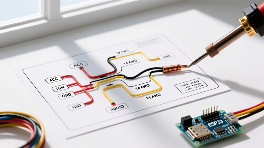
Schematic diagrams strip away the physical reality of the vehicle to show the pure logical flow of electricity. In a schematic, a 15-foot run of 10 AWG wire connecting a battery to a winch solenoid is represented by a simple, short straight line.
Vehicle Application: Schematics are your primary tool for understanding how a circuit operates. If you are diagnosing why the cooling fans on a GM LS-swapped vehicle only run on high, the schematic will reveal the series-parallel relay logic, the grounding triggers from the Engine Control Module (ECM), and the inline thermal fuses. They use standardized IEEE/IEC symbols for relays, diodes, resistors, and transistors.
Pro-Tip for CAN Bus Systems: In modern schematics, data lines (CAN-High and CAN-Low) are often drawn as parallel lines terminating in a 120-ohm resistor at each end of the bus. If your OBD2 scanner won't communicate, check the schematic for the exact location of the terminating resistors, often hidden inside the instrument cluster or the ECU itself.
2. Wiring Harness and Routing Diagrams (The Physical Map)
While schematics show logic, harness diagrams show physical geography. These diagrams illustrate how wires are bundled into looms, where they pass through the firewall, which grommets they use, and where the inline splice packs (like GM's flat-blade splice packs) are physically taped inside the harness.
Vehicle Application: Essential for physical repairs and aftermarket installations. If you need to tap into the left-rear turn signal wire to install a trailer brake controller module, the routing diagram tells you exactly which branch of the harness drops down behind the driver-side C-pillar, saving you from peeling back the entire interior carpet. They also identify harness tape colors and corrugated tubing diameters.
3. Connector Pinout and Block Diagrams (The Interface Guide)
Block diagrams focus entirely on connection points, modules, and plug faces. In automotive terms, these are the "Connector Cavity" charts. They map out exactly which wire color and gauge inserts into which specific numbered pin on an ECU, Transmission Control Module (TCM), or a standard 7-way RV blade connector.
Vehicle Application: Mandatory for bench-testing sensors or building custom adapter harnesses. For example, if you are repinning a Deutsch DT 12-pin connector for a snowplow setup, the block diagram ensures the 12V+ battery feed aligns perfectly with the heavy-duty 10 AWG pins, while the low-current LED indicator wires are routed to the smaller 18 AWG cavities.
4. Ground Distribution Diagrams (The Return Path Matrix)
Often overlooked by amateurs, ground distribution diagrams map every single ground point (often labeled G101, G204, etc.) to its physical bolt location on the vehicle chassis or engine block. In a 12V DC vehicle system, the ground return path is just as critical as the positive supply.
Vehicle Application: Crucial for diagnosing "ghost" electrical issues. A classic failure mode in older Jeep Wranglers (TJ/LJ era) is the fuel pump relay failing to engage due to a corroded G101 ground located behind the right kick panel. Without a ground distribution matrix, a mechanic might replace the fuel pump, the relay, and the ignition switch before realizing the chassis ground bolt was rusted.
Diagram Selection Matrix: Matching the Fault to the Document
Using the wrong diagram type wastes hours of diagnostic time. Refer to this matrix to select the correct documentation for your specific automotive or RV scenario.
| Diagnostic / Repair Scenario | Primary Diagram Type | Secondary Diagram Type | Key Data Points to Extract |
|---|---|---|---|
| Parasitic battery drain (over 50mA) | Schematic | Ground Distribution | Fuse assignments, sleep-mode relay triggers, module wake-up wires. |
| Installing a 3000W inverter in an RV | Routing / Harness | Schematic | Firewall grommet sizes, existing heavy-gauge wire paths, chassis ground bolt locations. |
| Trailer 7-way plug has no running lights | Connector Pinout (Block) | Schematic | Pin 4 (Tail/Marker) wire color, upstream lighting control module pinout. |
| ECU throwing P0131 (O2 Sensor Low Voltage) | Connector Pinout | Ground Distribution | Sensor signal pin cavity, shared sensor ground location on the engine head. |
Real-World Case Study: Upgrading a Golf Cart to Lithium Power
To understand how these types of electrical wiring diagrams interact, consider a common DIY project: converting a 36V lead-acid EZ-GO TXT golf cart to a 36V lithium iron phosphate (LiFePO4) battery system using a 105Ah drop-in pack and a Lester Summit onboard charger.
Step 1: The Schematic Phase (Logic)
Before cutting a single wire, you review the cart's master schematic. You identify that the original setup uses a heavy-duty solenoid triggered by the micro-switch in the accelerator box. The schematic reveals that the solenoid coil draws 2.5 amps on the trigger circuit. Because the new lithium BMS (Battery Management System) has a low-current pre-charge circuit, you use the schematic to design a bypass using a 10-ohm, 50-watt power resistor to prevent the BMS from tripping its short-circuit protection when the main solenoid slams shut.
Step 2: The Routing Phase (Physical)
The original lead-acid setup used 2 AWG welding cable routed under the seat pan. The routing diagram confirms the path, but you note that the sharp 90-degree bend near the motor controller requires upgrading to ultra-flexible silicone-jacketed 1 AWG wire to prevent insulation cracking from cart vibration. You also use the routing map to find a dry, ventilated cavity under the rear cowl to mount the 150A Class-T fuse, keeping it within 18 inches of the positive battery terminal as required by ABYC and automotive safety standards.
Step 3: The Pinout Phase (Interfaces)
The Lester Summit charger communicates with the cart via a 3-pin RXV/Club Car style connector. The block diagram ensures you map the charger's CAN-High, CAN-Low, and Ground wires to the exact corresponding pins on the cart's main harness adapter, ensuring the charger recognizes the BMS state-of-charge data.
Industry Standards Governing Vehicle Diagrams
When reading professional automotive and RV diagrams, you will encounter standardized color codes and line types dictated by industry bodies. According to the SAE International J1128 standard for low-tension primary cable, wire colors are abbreviated (e.g., BK for Black, RD for Red, GN for Green). Furthermore, the National Electrical Code (NEC) Article 551 strictly governs RV park and internal RV 120V/12V wiring separation, which is heavily reflected in modern RV harness routing diagrams to prevent inductive interference between AC shore power and DC data lines.
Frequently Asked Questions
Why do factory service manuals use both schematics and harness diagrams?
Factory manuals (like those from Helm Incorporated for Ford/GM) use schematics for the engineering logic and harness diagrams for the assembly line workers. A technician needs the schematic to diagnose a faulty logic gate in a BCM (Body Control Module), but needs the harness diagram to know that the wire physically splices into a waterproof gel-crimp connector located three inches behind the headlight assembly.
Can I use a standard house wiring diagram for my camper van build?
No. Residential wiring diagrams follow AC single-phase split-phase logic (120V/240V) and NEC Article 210 branch circuit rules. Camper vans and RVs utilize a hybrid of 12V/24V DC automotive standards (SAE) and 120V AC marine/RV standards (NEC Article 551). Using a residential diagram for the DC side will result in catastrophic undersizing of wire gauges, as DC voltage drop calculations require much thicker copper than equivalent AC amperage loads.
Final Diagnostic Advice
Mastering the different types of electrical wiring diagrams is the dividing line between a parts-swapper and a true diagnostic technician. Always verify the diagram's revision date—manufacturers frequently issue Technical Service Bulletins (TSBs) mid-year that alter splice pack locations or update ground points to resolve factory harmonic vibration issues. Keep a digital multimeter (like a Fluke 88V automotive meter) handy to verify that the physical reality of the harness matches the paper schematic, and never trust a wire color blindly without a pinout verification.