
The Blueprint of Climate Control: Navigating HVAC Schematics
When a split-system air conditioner fails in the peak of summer, the difference between a two-hour diagnostic marathon and a twenty-minute targeted repair lies in your ability to read HVAC electrical wiring diagrams. Modern systems in 2026 are more efficient than ever, integrating variable-speed compressors and advanced communicating control boards. However, the foundational logic of standard 24V control circuits and 240V high-voltage compressor paths remains the bedrock of residential and light-commercial troubleshooting.
Before touching a multimeter, technicians must understand that manufacturers provide two distinct types of wiring diagrams. Confusing them is the most common mistake made by entry-level techs.
Pictorial vs. Ladder (Schematic) Diagrams
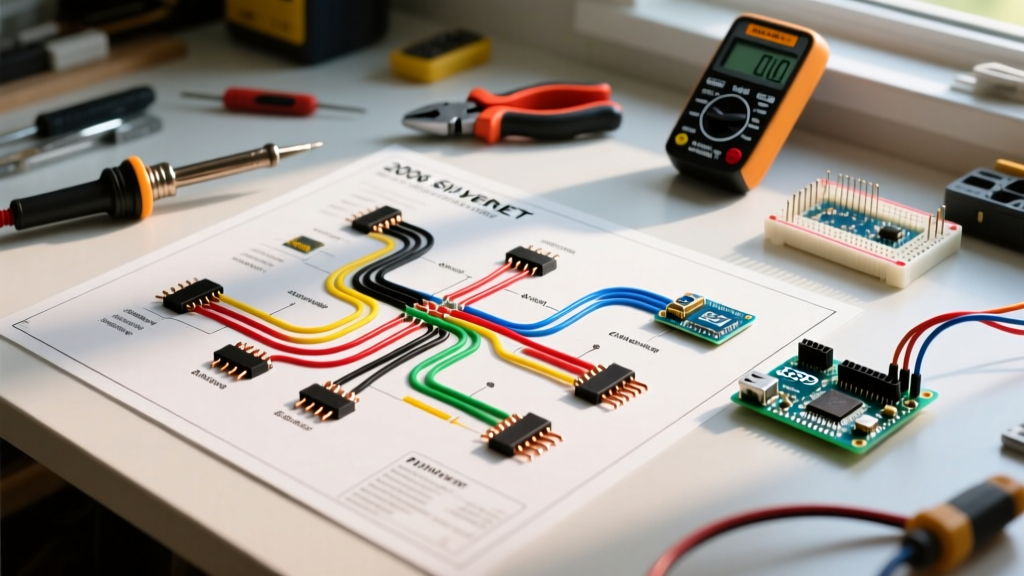
- Pictorial Diagrams: These show the physical layout of the components and how wires are routed through the cabinet. They are invaluable during installation but nearly useless for logical troubleshooting because they do not illustrate the electrical sequence of operations.
- Ladder (Schematic) Diagrams: This is your troubleshooting bible. Ladder diagrams arrange the circuit logically, with the high-voltage power lines on the outer vertical rails (L1 and L2) and the control circuits forming the horizontal 'rungs'. They reveal exactly which switches, relays, and safety limits must close to energize a specific load.
Decoding the Legend: Critical Symbols for 2026 Systems
Every manufacturer (from Trane and Lennox to Bosch and Daikin) includes a legend on the schematic. While basic symbols are universal, modern high-efficiency systems introduce new components. Below is a reference matrix for the symbols you will encounter most frequently when tracing faults.
| Component | Standard Symbol | Function in Circuit | Common Failure Mode |
|---|---|---|---|
| Contactor Coil | Circle with 'M' or 'C' | Energizes high-voltage contacts to start compressor/fan | Coil shorts (blows fuse) or opens (no engagement) |
| Limit Switch | Normally Closed (NC) contacts | Breaks 24V circuit if furnace overheats | Trips due to restricted airflow; fails to reset |
| Thermistor | Resistor with a diagonal line | Provides variable resistance based on temperature | Drifts out of calibration, causing short-cycling |
| Dual Run Capacitor | Two parallel lines with a gap | Provides phase shift for compressor and fan motors | Microfarad (µF) drops below 6% tolerance; bulges |
| ECM Motor Module | Box with multiple pinouts | Controls variable-speed blower via DC logic | Internal thermistor fails; control board drops signal |
Step-by-Step Troubleshooting: Tracing the 24V Control Circuit
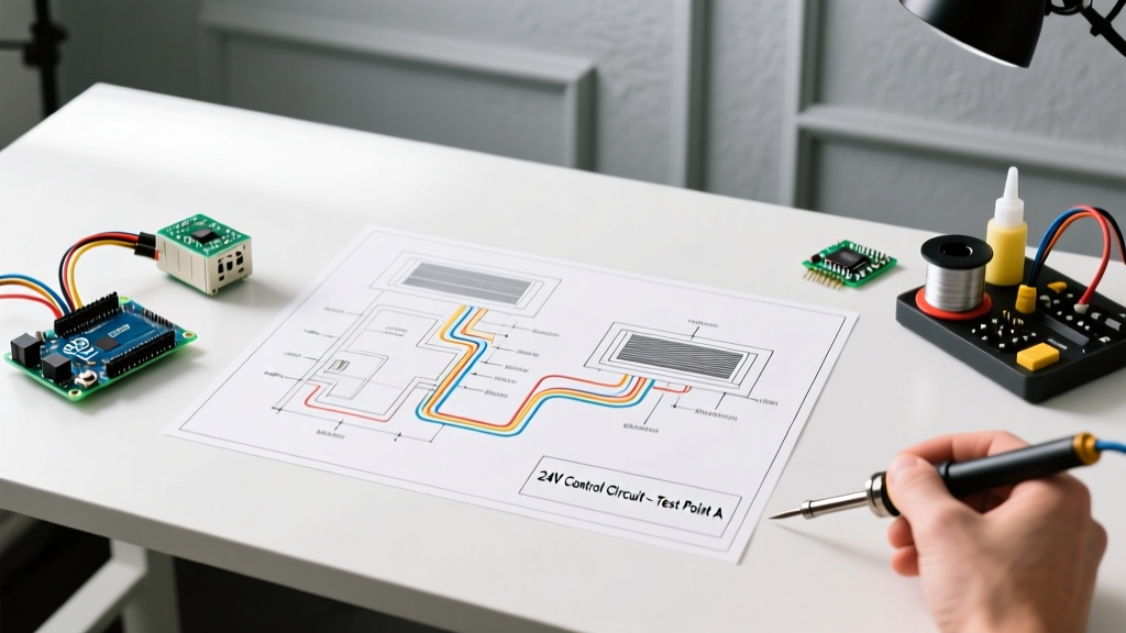
The most frequent service call is 'No Cooling.' The thermostat is calling for Y (compressor) and G (blower), but the outdoor unit is dead. Here is how to use the ladder diagram to isolate the fault using a reliable tool like the Fluke 116 HVAC Multimeter (approx. $180).
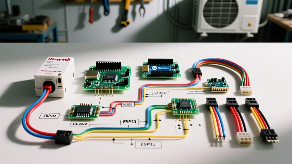
- Verify the Source: Set your meter to VAC. Measure between the R (24V Hot) and C (24V Common) terminals at the air handler control board. You should read between 24V and 28V AC. If you read 0V, check the 40VA control transformer (e.g., Honeywell AT72D1683) and the 3A ATC blade fuse on the board.
- Trace the Call for Cooling: With the thermostat calling for cooling, measure between Y and C at the control board. You should see ~24VAC. If you have 24VAC at the board's Y terminal but the outdoor unit is dead, the fault is in the wiring between the air handler and the condenser.
- Check the Condenser Coil: Go to the outdoor unit. Remove the access panel (ensure Lockout/Tagout procedures are followed for the high-voltage side). Measure between the Y and C wires landing on the contactor coil. If you have 24VAC here, but the contactor is not pulling in, the contactor coil is defective.
Pro Tip: Never jump 24V R to Y at the outdoor unit to force the compressor on unless you have verified the high-pressure switch and low-pressure switch are closed on the schematic. Bypassing safeties can lead to catastrophic compressor failure or a ruptured refrigerant line.
Real-World Scenario: Diagnosing a Blown 3A Control Board Fuse
A blown 3-amp automotive-style (ATC) fuse on the indoor control board is a symptom, not the root cause. The schematic shows that this fuse protects the 24VAC secondary side of the transformer. If you simply replace the fuse and power the system, it will likely blow again immediately.
The Diagnostic Framework:
- Step 1: Disconnect the Y wire (compressor call) from the control board and the C wire from the outdoor contactor coil.
- Step 2: Set your multimeter to Ohms (Ω). Measure the resistance across the contactor coil terminals in the outdoor unit. A healthy 24V coil (like the widely used Mars 10906 30A 1-Pole Contactor, approx. $22) should read between 10 and 30 ohms.
- Step 3: If the reading is below 5 ohms, the coil has an internal short. It is drawing excessive amperage, overwhelming the 3A fuse. Replace the contactor.
- Step 4: If the coil reads correctly (e.g., 18 ohms), the short is likely in the Y thermostat wire itself, perhaps where it rubs against a sharp sheet metal edge or was chewed by rodents. Perform a continuity test from the Y wire to the C wire and ground to find the short.
High-Voltage Side: Testing the Compressor and Capacitor
Once the 24V logic is verified, the schematic directs us to the high-voltage (208/230V) side. The most common point of failure here is the dual run capacitor. In 2026, premium capacitors like the AmRad Titan Pro HD (approx. $30 for a 45/5 MFD) are standard recommendations due to their superior thermal tolerance.
Capacitor Tolerance Matrix
Using a multimeter with a capacitance setting (or a dedicated tester like the Fieldpiece SC440), measure the microfarads (µF). Compare your reading to the nameplate rating. According to industry standards, a capacitor must be replaced if it falls outside the ±6% tolerance.
| Nameplate Rating | Minimum Acceptable (µF) | Maximum Acceptable (µF) | Action Required if Out of Range |
|---|---|---|---|
| 45 / 5 MFD | 42.3 / 4.7 | 47.7 / 5.3 | Replace immediately; compressor risks hard-starting |
| 35 / 5 MFD | 32.9 / 4.7 | 37.1 / 5.3 | Replace; fan motor may overheat and trip internal overload |
| 60 / 7.5 MFD | 56.4 / 7.05 | 63.6 / 7.95 | Replace; common on older 3-ton to 4-ton units |
Advanced Diagnostics: The Shift to Communicating Systems
As we move deeper into 2026, standard 24V AC ladder diagrams are being replaced by communicating system schematics in high-end installations (e.g., Carrier Infinity, Lennox S40, and Bosch IDS 2.0 heat pumps).
Troubleshooting these requires a fundamental shift in how you read the diagram. Instead of discrete 24V AC signals for Y, W, and G, communicating systems use a multiplexed DC signal (often pulsing between 15V and 30V DC) over two or three low-voltage wires to transmit digital data packets between the thermostat, air handler, and outdoor inverter board.
- The Trap: Attempting to measure a communicating bus with a standard VAC setting will yield erratic, useless readings.
- The Solution: Use the VDC setting on your meter. If the schematic indicates a DC bus, look for a steady or pulsing DC voltage (usually around 15-30V DC). If the voltage drops to 0V, the fault is either a shorted communication wire, a blown DC fuse on the main board, or a failed communication chip on the inverter drive.
Safety First: Adhering to Industry Standards
Troubleshooting live HVAC circuits carries inherent risks. The NFPA 70E Standard for Electrical Safety in the Workplace mandates strict protocols for working near exposed energized parts, including the use of appropriately rated PPE and CAT III or CAT IV multimeters. Furthermore, maintaining certifications through organizations like North American Technician Excellence (NATE) ensures that technicians are regularly tested on the latest schematic interpretations and safety protocols. For broader industry best practices and installation standards, the Air Conditioning Contractors of America (ACCA) provides essential manuals that dictate how these electrical systems should be integrated with ductwork and refrigerant circuits for optimal performance.
Summary Checklist for the Field
Keep this mental checklist when deploying HVAC electrical wiring diagrams on your next service call:
- Identify if you are looking at a pictorial (routing) or ladder (logic) diagram.
- Verify the 24VAC source at the transformer before tracing the circuit.
- Isolate the control circuit (24V) from the load circuit (240V) during diagnostics.
- Measure resistance (Ohms) on coils and continuity on switches to find opens and shorts.
- Verify capacitor microfarads against the ±6% tolerance rule.
- Recognize communicating DC buses and adjust your meter settings accordingly.
Mastering the schematic transforms you from a parts-changer into a true diagnostic technician, saving time, reducing callbacks, and ensuring system longevity.