
Mastering the Wiring Diagram for Electric Fan Troubleshooting
When an electric fan stops working, the immediate instinct is often to replace the entire unit. However, with a basic understanding of electrical circuits and a reliable wiring diagram for electric fan systems, you can isolate the failure point and repair the appliance for a fraction of the cost. Whether you are working on a 16-inch pedestal fan, a 52-inch ceiling fan, or an industrial exhaust blower, the underlying principles of AC induction motors remain remarkably consistent. This guide will teach you how to decode schematic diagrams, test individual components with a multimeter, and safely restore your fan to full operational capacity.
The Evolution of Fan Motors: PSC, Shaded Pole, and BLDC
Before diving into the schematic, it is critical to identify the motor type, as this dictates the complexity of the wiring diagram. As of 2026, the market is split between three primary technologies:
- Permanent Split Capacitor (PSC) Motors: The most common type in ceiling and high-end pedestal fans. They utilize a run capacitor to create a phase shift, providing high starting torque and multiple speed taps. The wiring diagram for a PSC motor will always feature a capacitor wired in series with the start winding.
- Shaded Pole Motors: Found in cheap, low-power desk fans and bathroom exhaust fans. They use a copper shading coil to create a rotating magnetic field. These diagrams are incredibly simple, often consisting of just a power cord, a basic switch, and the main winding. They lack a separate start winding or capacitor.
- Brushless DC (BLDC) Motors: Increasingly common in modern, energy-efficient smart fans. Instead of a simple analog wiring diagram, BLDC fans rely on an integrated Printed Circuit Board (PCB) to convert AC mains to DC and manage electronic commutation. Troubleshooting these requires PCB-level diagnostics rather than simple continuity checks.
This guide focuses primarily on PSC and Shaded Pole AC motors, which represent the vast majority of repairable, diagram-based troubleshooting scenarios.
Decoding the Standard PSC Wiring Diagram
A standard 3-speed PSC fan wiring diagram will typically show four main components: the main power input, the speed selector switch (usually a rotary or pull-chain type), the run capacitor, and the motor stator windings. Below is a breakdown of the standard wire color coding used by most North American and international manufacturers.
| Wire Color | Function / Connection Point | Typical Resistance to Common (Ω) |
|---|---|---|
| White | Common (Neutral / AC Line 2) | N/A (Baseline reference) |
| Black | Main Winding (High Speed) | 50Ω - 90Ω (Lowest resistance) |
| Blue | Medium Speed Tap | 110Ω - 150Ω |
| Red | Low Speed Tap / Start Winding | 160Ω - 250Ω (Highest resistance) |
| Yellow/Brown | Capacitor Connection (Start Winding) | Varies based on capacitor state |
Expert Insight: Never assume wire colors are universal. While the scheme above is standard for brands like Hunter, Hampton Bay, and Panasonic, some imported models use black for common and white for high speed. Always trace the physical wires back to the stator windings or rely on the manufacturer's specific schematic printed on the motor housing.
Step-by-Step Troubleshooting Using the Diagram
When a fan fails, the wiring diagram acts as your roadmap. By correlating physical symptoms with schematic nodes, you can eliminate guesswork. Always ensure the fan is unplugged or the circuit breaker is locked out before proceeding. For comprehensive safety protocols, refer to the OSHA Lockout/Tagout standard 1910.147.
Scenario 1: Fan Hums but Blades Will Not Spin
The Symptom: You turn the fan on, hear a distinct 60Hz electrical hum, and the motor gets warm, but the blades remain stationary. If you manually push the blades, they might start spinning sluggishly. The Diagram Diagnosis: This points directly to the Start Winding circuit or the Run Capacitor. In a PSC diagram, the capacitor is in series with the start winding. If the capacitor fails open, no phase shift occurs, resulting in zero starting torque. The Fix:
- Locate the capacitor on the diagram (usually a 1.0µF to 2.5µF, 250VAC or 400VAC component for pedestal fans).
- Disconnect the capacitor and test it with a multimeter set to capacitance (µF). A reading more than 10% below the rated microfarad value indicates failure.
- Replace with an identical spec capacitor (Cost: $4 to $12). Do not substitute a DC electrolytic capacitor; it must be an AC motor run capacitor (metalized polypropylene film).
Scenario 2: Fan is Completely Dead (No Hum, No Movement)
The Symptom: The fan shows absolutely no signs of life on any speed setting. The Diagram Diagnosis: The failure is on the Common line before the circuit splits into the speed taps, or the internal Thermal Fuse has blown. Most modern fan motors embed a non-resettable thermal fuse (rated between 115°C and 130°C, 2 Amps) deep inside the motor windings to prevent fires in case of overheating. The Fix:
- Test the power cord for continuity from the plug prongs to the switch input.
- If the cord is good, consult the diagram to locate the thermal fuse (usually represented by a small rectangle with a line through it, wired in series with the white/common wire).
- Accessing the thermal fuse requires cutting the fiberglass sleaving near the stator windings. Test for continuity. If open, the fuse is blown.
- Solder a new thermal fuse (Cost: $2 to $5). Warning: Do not use a standard soldering iron directly on the fuse leads, as the heat will blow the new fuse instantly. Use a heat sink (like an alligator clip) between the solder joint and the fuse body, or use spot welding/crimping.
Scenario 3: Fan Only Runs on High Speed
The Symptom: Switching to Medium or Low does nothing, or the fan stays at maximum RPM. The Diagram Diagnosis: The Speed Selector Switch has failed internally, or the intermediate winding taps (Blue/Red wires) have broken off the stator bobbin. The Fix:
- Set the multimeter to continuity mode.
- Probe the switch terminals according to the diagram. In the 'Low' position, continuity should exist between the Line In and the Red wire terminal. In 'Medium', between Line In and Blue.
- If the switch fails to show continuity on lower settings, replace the rotary or pull-chain switch assembly (Cost: $8 to $15).
Multimeter Testing Reference Matrix
Use this diagnostic matrix to quickly verify component health against the wiring diagram nodes. Ensure all components are isolated from the circuit before testing.
| Component | Multimeter Setting | Expected Healthy Reading | Failure Mode Indicator |
|---|---|---|---|
| Run Capacitor | Capacitance (µF) | Within ±5% of printed rating | Reads 0, OL, or >10% drop |
| Main Winding (High) | Resistance (Ω) | 50Ω - 100Ω | OL (Open) or <10Ω (Short) |
| Thermal Fuse | Continuity / Resistance | < 1.0Ω (Beep) | OL (Open / Blown) |
| Speed Switch | Continuity | Beep on correct output pin | No beep on specific settings |
Compliance and Safety Standards
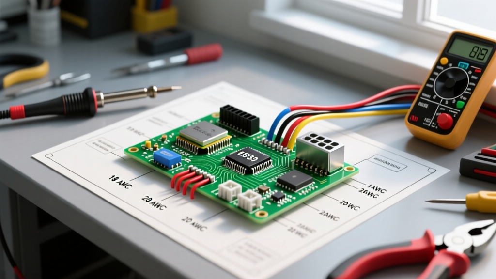
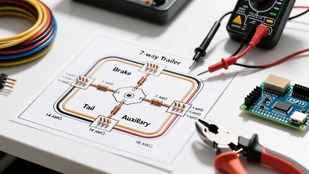
When repairing or modifying electric fan wiring, adherence to electrical codes is non-negotiable. According to the National Electrical Code (NFPA 70), branch circuits supplying fixed appliances like ceiling fans must be properly grounded and protected by the correct overcurrent device (typically a 15A or 20A breaker). Furthermore, internal fan wiring must utilize appropriate wire gauges; 18 AWG stranded copper is standard for internal motor leads, while branch circuit connections in the ceiling canopy must use a minimum of 14 AWG solid copper.
The U.S. Department of Energy's Motor Systems guidelines also emphasize that improper capacitor replacement or bypassing thermal fuses can lead to catastrophic motor burnout, reducing overall system efficiency and posing severe fire hazards. Always replace components with exact OEM equivalents.
Frequently Asked Questions (FAQ)
Can I use a higher µF capacitor to make my fan spin faster?
No. While a slightly higher microfarad rating (e.g., swapping a 1.5µF for a 2.0µF) might temporarily increase starting torque, it will cause the start winding to draw excessive current. This leads to overheating, insulation breakdown, and eventual motor failure. Always stick to the exact µF and voltage rating specified on the original capacitor or the wiring diagram.
Why does my fan wiring diagram show a black box labeled 'PCB'?
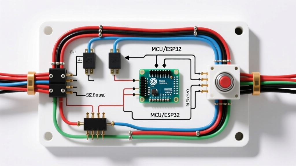
If your diagram includes a PCB (Printed Circuit Board) block, you are likely working on a modern BLDC fan or a fan with integrated smart features (Wi-Fi, remote control receivers). You cannot troubleshoot a PCB with simple continuity tests. If the PCB is faulty, it must be replaced as a single modular unit, which typically costs between $25 and $60 depending on the brand.
How do I test a shaded pole motor without a capacitor?
Shaded pole motors only have one main winding and a copper shading ring. To test it, simply check the continuity of the main winding across the two power leads. You should read a moderate resistance (typically 200Ω to 600Ω depending on the motor's physical size). If it reads OL, the internal thermal fuse or the winding itself is open, and the motor must be replaced.