
Wiring residential motors—whether for an HVAC condenser, a furnace blower, or a deep well pump—requires more than just connecting colored wires to terminals. It demands a strict adherence to home electrical wiring diagrams and a deep understanding of motor control circuits. As of 2026, the residential landscape has shifted heavily toward ECM (Electronically Commutated Motors) to meet updated Department of Energy efficiency mandates, making legacy PSC (Permanent Split Capacitor) schematics increasingly rare in new installations but still vital for troubleshooting older systems.
This comprehensive motor wiring tutorial will decode the symbols, safety protocols, and National Electrical Code (NEC) requirements found in standard residential motor diagrams, giving you the actionable expertise to wire, test, and troubleshoot with confidence.
The Anatomy of Residential Motor Wiring Diagrams
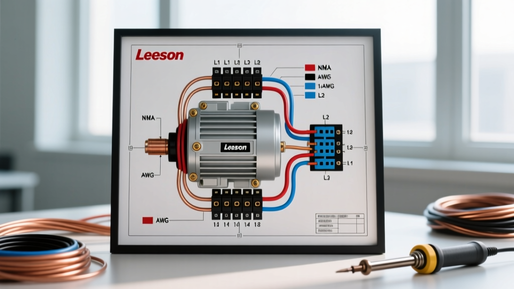
Before touching a wire stripper, you must be able to read the schematic typically located on the inside of the HVAC condenser access panel or well pump control box. Home electrical wiring diagrams for motors rely on standardized NEMA and IEC symbols.
- L1 and L2: Represent the 240V line voltage feeds from the main breaker panel.
- T1, T2, T3, T4: Represent the load side terminals, usually feeding into a contactor or directly to the motor windings.
- C, S, R: Found on PSC compressor and blower diagrams, representing Common, Start, and Run winding terminals.
- Contactor (K1): The heavy-duty relay that switches 240V power to the motor based on a 24V thermostat signal.
- Thermal Overload (OL): A bimetallic or electronic safeguard that breaks the control circuit if the motor draws excessive amperage.
Always cross-reference the physical wiring against the manufacturer's specific schematic. A generic diagram found online may not account for factory-installed accessories like crankcase heaters, hard-start kits, or phase monitors.
Step-by-Step Tutorial: Wiring a 240V PSC Condenser Fan Motor
Let us walk through the physical wiring of a standard 1/4 HP, 240V Permanent Split Capacitor (PSC) condenser fan motor, a common scenario when reading home electrical wiring diagrams for HVAC replacements.
Step 1: Circuit Sizing and Wire Selection
According to NFPA NEC Article 430.52, the branch-circuit short-circuit and ground-fault protective device for an AC motor can be sized up to 175% of the motor's Full Load Amps (FLA). If your fan motor has an FLA of 1.2A and the compressor draws 18A, the combined Minimum Circuit Ampacity (MCA) dictates the wire size. For a standard 30A double-pole breaker, you must use 10 AWG copper THHN routed through a dedicated 3/4-inch liquid-tight flexible metal conduit (LFMC).
Step 2: Contactor and Line Voltage Wiring
- Terminate the 10 AWG L1 and L2 line wires into the top lugs of the 30A double-pole contactor.
- Run 10 AWG pigtails from the bottom (load) lugs of the contactor (T1 and T2) to the motor's Line terminals.
- Ensure the ground wire (10 AWG bare or green) is bonded directly to the condenser chassis ground lug, not the contactor.
Step 3: Control Circuit Integration (24VAC)
The 24V control signal originates from the furnace control board or air handler. Using 18/5 thermostat wire, connect the Y (Yellow) wire to the contactor coil's positive terminal and the C (Common) wire to the coil's negative terminal. When the thermostat calls for cooling, 24VAC energizes the coil, pulling the high-voltage contacts closed and starting the motor.
Capacitor Wiring and Critical Safety Protocols
Run capacitors provide the phase shift necessary for a PSC motor to generate starting torque. A typical residential dual run capacitor (e.g., AmRad or Titan Pro 45/5 MFD, 370V/440V) features three terminals: C (Common), FAN, and HERM (Hermetic/Compressor).
When analyzing home electrical wiring diagrams for capacitor connections, the brown wires from the fan motor typically route directly to the FAN terminal, while the brown wire with a white stripe routes to the C terminal. Warning: A failed capacitor can retain a lethal electrical charge long after power is disconnected. Before touching any terminals, use a 20,000-ohm, 2-watt bleeder resistor across the terminals to safely discharge the stored voltage, and verify with a CAT III-rated multimeter like the Fluke 117.
For in-depth testing procedures, refer to Fluke's authoritative guide on testing motor capacitors using capacitance mode to check for microfarad degradation.
The 2026 Shift: ECM Motor Wiring Diagrams
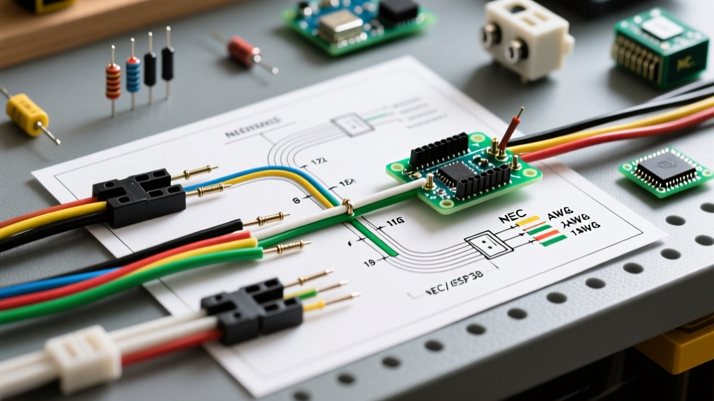
With the U.S. Department of Energy enforcing stricter SEER2 ratings, the industry has pivoted to ECM motors (such as the Genteq X13 or GE ECM 3.0). The home electrical wiring diagrams for these motors look vastly different from legacy PSC schematics. Instead of simple line-voltage connections, ECMs use a low-voltage logic harness.
A standard 5-pin ECM control plug requires:
- Pin 1 (L1): 120V or 240V Hot (depending on model)
- Pin 2 (L2): 120V or 240V Hot
- Pin 3 (Neutral): Grounded Neutral
- Pin 4 (24VAC Hot): Control signal from thermostat (Y or G)
- Pin 5 (24VAC Common): Control common
Unlike PSC motors, you cannot reverse the rotation of an ECM motor by swapping L1 and L2. Rotation is dictated by the internal microprocessor. If an ECM is running backward or failing to start, the issue is almost always a failed control module, a missing 24VAC signal on Pin 4, or a blown 3A fuse on the air handler control board.
Troubleshooting Matrix: Common Motor Wiring Failures
Use this diagnostic matrix when your physical wiring matches the home electrical wiring diagram, but the motor fails to operate correctly.
| Symptom | Schematic Node to Check | Multimeter Setting | Expected Reading | Corrective Action |
|---|---|---|---|---|
| Motor hums loudly, shaft won't turn | Start Winding (S to C) | Ohms (Low Range) | 2.0 Ω - 8.0 Ω | Test run/start capacitor for MFD drop. If capacitor is good, check for a seized bearing or failed centrifugal switch. |
| Blower runs, but pushes no air (backward) | T1 / T2 Line Reversal | N/A | N/A | Swap L1 and L2 at the contactor load side (PSC motors only). Verify factory rotation arrow on motor housing. |
| Thermal overload trips after 3 minutes | Amp Draw vs Diagram FLA | AC Amps (Clamp) | Less than FLA + 10% | Check for binding blower wheel, dirty condenser coils, or severe voltage drop (under 208V on a 240V circuit). |
| Contactor chatters or buzzes | 24VAC Coil Terminals | AC Volts | 22V - 26V AC | Clean contactor mating surfaces. Check for loose 18/5 thermostat wire connections causing voltage sag under load. |
Code Compliance: Grounding and Bonding Motors
A frequent error DIYers make when following home electrical wiring diagrams is confusing the equipment grounding conductor (EGC) with the neutral wire. Per U.S. Department of Energy Motor Systems guidelines and NEC Article 250, the motor chassis must be bonded to the main panel's ground bus. In a 240V motor circuit, a neutral wire is not required unless the system includes a 120V accessory, such as a condenser crankcase heater or a smart thermostat Wi-Fi module. If a neutral is present, it must be isolated on a dedicated neutral bus bar, never bonded to the ground at the subpanel or disconnect switch.
Frequently Asked Questions (FAQ)
Can I use a 40A breaker for a motor with a 30A MCA?
No. The Maximum Overcurrent Protection (MOCP) listed on the equipment nameplate is the absolute legal limit. If the nameplate specifies a 30A MOCP, installing a 40A breaker violates NEC Article 110.3(B) and voids the manufacturer's warranty, creating a severe fire hazard.
Why does my wiring diagram show a "Hard Start Kit"?
Hard start kits (a start capacitor paired with a potential relay) are used to provide an extra phase-shifted torque boost to aging compressors or units operating in extreme heat. The wiring diagram will show the start capacitor wiring in parallel with the run capacitor, routed through the potential relay's NC (Normally Closed) contacts.
What happens if I wire a 208V motor to a 240V supply?
While many residential motors are dual-rated (208/230V), running a strict 208V motor on 240V will cause the windings to overheat, drastically shortening the motor's lifespan and tripping the internal thermal overload. Always verify the supply voltage at the disconnect before finalizing the wiring.