
Understanding Power Delivery in Dual Electronics Head Units
Installing an aftermarket head unit requires more than just matching speaker wires; it demands a rigorous approach to 12V DC power delivery and circuit protection. When working with popular budget-friendly and feature-rich units like the Dual Electronics XDM68BT or the XDVD276BT, understanding the underlying electrical architecture is critical. These units typically draw between 8A and 12A at peak volume, with inrush currents during boot-up that can stress poorly protected circuits. From a Panel & Breaker Guide perspective, the vehicle's interior fuse block (often tied to the Body Control Module or BCM) serves as your primary distribution panel. Properly integrating your stereo into this panel using the correct overcurrent protection—whether standard blade fuses or automatic reset circuit breakers—ensures long-term reliability and prevents catastrophic wire meltdowns.
In this guide, we will break down the exact wiring diagram for Dual car stereo units, map the EIA standard color codes, and detail how to safely tap your vehicle's fuse panel while maintaining proper breaker protection.
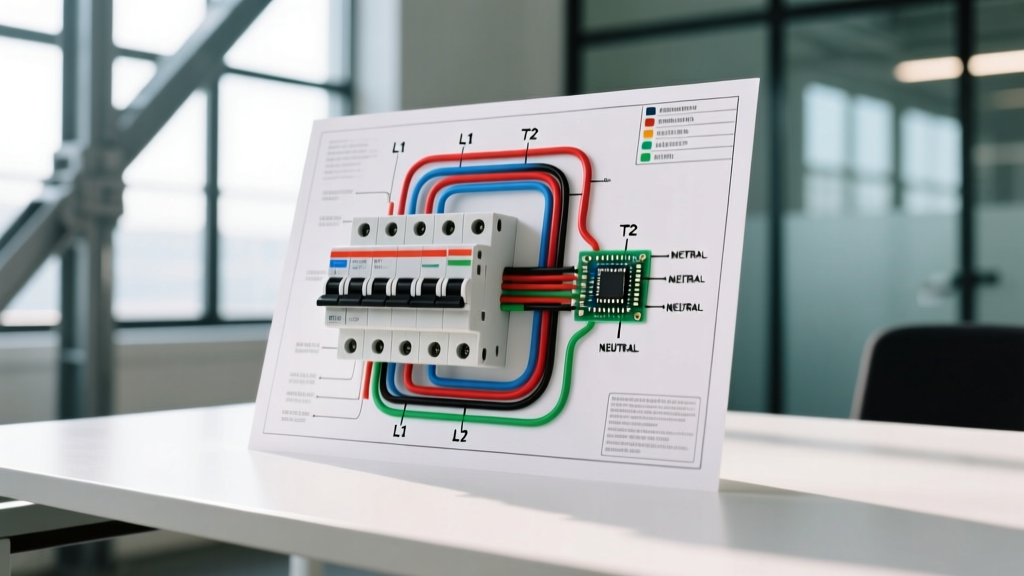
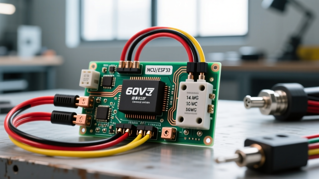
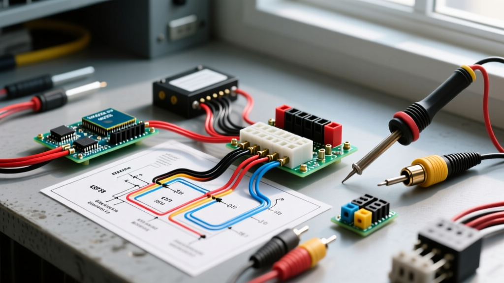
The Core Wiring Diagram for Dual Car Stereo Head Units
Dual Electronics adheres to the Consumer Technology Association (CTA) and EIA RS-770 standard color codes for aftermarket car audio. This standardization means that whether you are wiring a single-DIN Dual XDM16 or a double-DIN multimedia receiver, the power and speaker harness colors remain consistent. Below is the definitive mapping for the primary power and accessory harness.
| Wire Color | Function | Panel/Breaker Connection Point | Recommended Protection |
|---|---|---|---|
| Yellow | Constant 12V+ (Memory/ECU) | Battery or Constant Fuse Panel Tap | 10A ATC Inline Fuse |
| Red | Switched 12V+ (Ignition/ACC) | Ignition-Switched Fuse Panel Tap | 10A ATC Inline Fuse |
| Black | Chassis Ground (-) | Bare metal chassis point (No Paint) | N/A (Ensure < 0.1V drop) |
| Blue/White | Amplifier/Antenna Turn-On | Spliced to Amp Remote / Relay Coil | 2A Inline Fuse |
| Orange/White | Illumination / Dimmer | Headlight Switch Circuit (Optional) | 5A Inline Fuse |
When referencing a standard wiring diagram for Dual car stereo units, the most common point of failure occurs when installers swap the Yellow and Red wires. While the stereo will turn on, the Yellow wire (which powers the volatile memory for radio presets and clock settings) will lose power when the ignition is turned off, causing the unit to reset every time you start the car.
Panel & Breaker Integration: Protecting the 12V DC Circuit
In residential electrical work, we rely on panel-mounted circuit breakers to protect branch circuits. In automotive 12V DC systems, the 'panel' is the vehicle's fuse block, and the 'breakers' are either disposable blade fuses or auto-resetting thermal circuit breakers. According to Littelfuse Automotive Circuit Protection guidelines, overcurrent protection must be placed as close to the power source as possible.
Inline Fuses vs. Automotive Circuit Breakers
For a standard Dual car stereo drawing under 15A, a standard ATO/ATC blade fuse is the industry standard. However, if you are routing the main power wire from the engine bay battery (often done if the interior fuse panel lacks adequate constant 12V capacity), you must install a main breaker or fuse within 18 inches of the battery positive terminal.
- Standard Blade Fuses (ATC/ATO): Inexpensive ($0.50 - $1.00 each), reliable, and require manual replacement when blown. Best for interior fuse panel taps using an Add-A-Circuit.
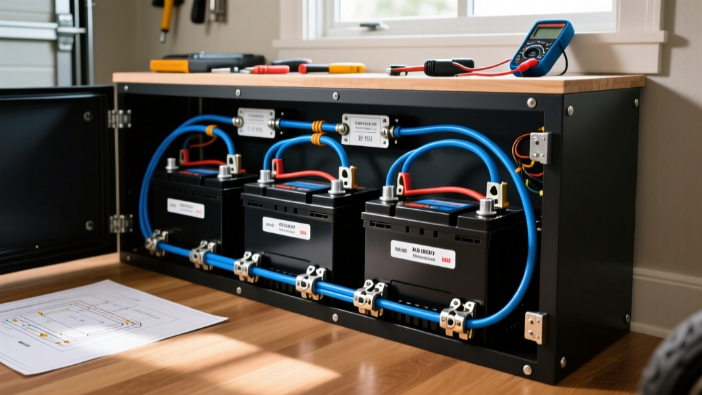
- Type II Cycling Circuit Breakers: Priced around $12 - $18. These use a bi-metallic strip that trips under thermal overload and automatically resets once the circuit cools. Brands like Eaton Bussmann manufacture these for high-vibration environments. They are ideal for long wire runs where a short circuit might be intermittent.
Pro-Tip: Never use a circuit breaker with a higher amperage rating than the wire's ampacity. A 12 AWG wire is rated for roughly 20A in chassis wiring; therefore, your breaker or fuse must never exceed 20A, even if the stereo only draws 10A. The protection device guards the wire, not just the load.
Step-by-Step Fuse Panel Tapping Procedure
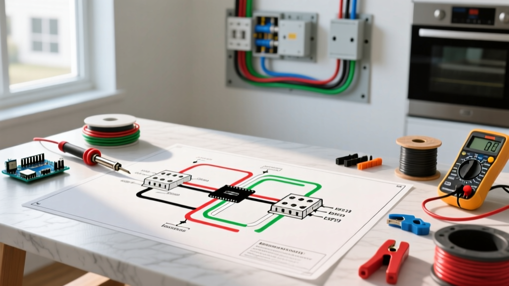
To safely integrate the Red (switched) and Yellow (constant) wires into your vehicle's interior fuse panel without splicing or cutting factory wiring, use a Mini-Add-A-Circuit or ATO-Add-A-Circuit fuse tap kit. This effectively turns a single fuse slot into a protected micro-panel for your aftermarket stereo.
- Identify the Circuits: Using a digital multimeter (like the Fluke 87V), probe the fuse panel with the ignition OFF. A slot reading 12V is your Constant (Yellow) source. Turn the ignition to the ACC position; a slot that now reads 12V is your Switched (Red) source.
- Verify Amperage Headroom: Ensure the factory circuit you are tapping has at least 5A of unused capacity. Do not tap into safety-critical circuits like airbags (SRS), ABS, or ECU fuel injection relays. Stick to accessory sockets, power mirrors, or interior lighting circuits.
- Insert the Fuse Tap: Plug the Add-A-Circuit into the identified slot. The tap features two fuse slots: one for the original factory circuit, and one for your new stereo wire.
- Crimp and Seal: Connect the tap's pigtail to your stereo's harness using Ancor marine-grade heat shrink butt connectors. Avoid 3M Scotchlok T-taps, which are notorious for corrosion and vibration-induced disconnects in automotive environments.
Calculating Wire Gauge and Voltage Drop
While Dual head units typically ship with 18 AWG power pigtails, extending these wires across a large vehicle (like a full-size SUV or van) requires careful voltage drop calculations. According to Fluke Automotive Voltage Drop Testing standards, a 12V DC circuit should not experience a voltage drop greater than 3% (0.36V) under full load.
If your Dual XDVD276BT is drawing 10A and you need to run a 15-foot extension from the battery to the dash, 18 AWG wire will result in a voltage drop of approximately 0.6V, which can cause the stereo to reboot or shut down during heavy bass transients. In this scenario, you must upgrade the extension wire to 14 AWG or 12 AWG to maintain voltage stability, while keeping the final 10A fuse intact at the battery terminal.
Real-World Failure Modes and Edge Cases
Even with a perfect wiring diagram for Dual car stereo units, real-world installations encounter edge cases. Here is a troubleshooting matrix based on common panel and breaker failures:
| Symptom | Probable Electrical Cause | Panel/Breaker Solution |
|---|---|---|
| Stereo resets when engine cranks | Yellow wire tapped to a circuit that drops voltage during starter engagement. | Move Yellow wire tap to a true constant 12V source, or install a 1-Farad capacitor with a diode to hold memory voltage. |
| Inline fuse blows instantly on ACC | Red wire pinched behind the DIN sleeve, shorting to the metal dash chassis. | Inspect the DIN cage installation. Ensure the metal sleeve is wrapped in Tesa tape to prevent chassis grounding. |
| Alternator whine in speakers | Ground loop caused by high resistance on the Black ground wire. | Do not ground to the radio cage. Run an 18 AWG ground wire directly to a structural chassis bolt, sanding away paint to bare metal. |
| Thermal breaker clicks repeatedly | Breaker is mounted in a high-heat zone (near HVAC heater core) causing premature thermal tripping. | Relocate the auto-reset breaker to a cooler zone, or switch to a standard ATC blade fuse which is immune to ambient cabin heat. |
Expert FAQs on Dual Stereo Wiring
Can I wire the Yellow and Red wires together to a single constant 12V source?
Technically, yes. If you wire both the Yellow and Red wires to a constant 12V battery source, the Dual stereo will function. However, the unit will never receive the 'shut off' signal from the ignition. You will have to manually power down the stereo using the front panel button every time you exit the vehicle. If you forget, the unit will drain your car battery within 24 to 48 hours due to the standby current draw of the internal clock and ECU memory.
Does the Dual XDM68BT require a relay for the power antenna?
The Blue/White wire on the Dual harness outputs a maximum of 300mA (0.3A). This is sufficient to trigger a standard automotive 12V relay coil, but it is not enough to directly power a high-draw motorized mast antenna or a high-current cooling fan. Always use the Blue/White wire to trigger the coil of a 30A Bosch-style relay, and pull the heavy current directly from a fused panel source.
What is the SAE standard for automotive wire insulation?
When extending your Dual stereo harness, ensure you are using SAE J1128 or SAE J1113 compliant automotive primary wire (like GXL or TXL). These feature cross-linked polyethylene insulation that resists melting against hot HVAC ducts and engine bay temperatures, unlike standard THHN residential wire which will degrade rapidly in a vehicle's harsh environment.