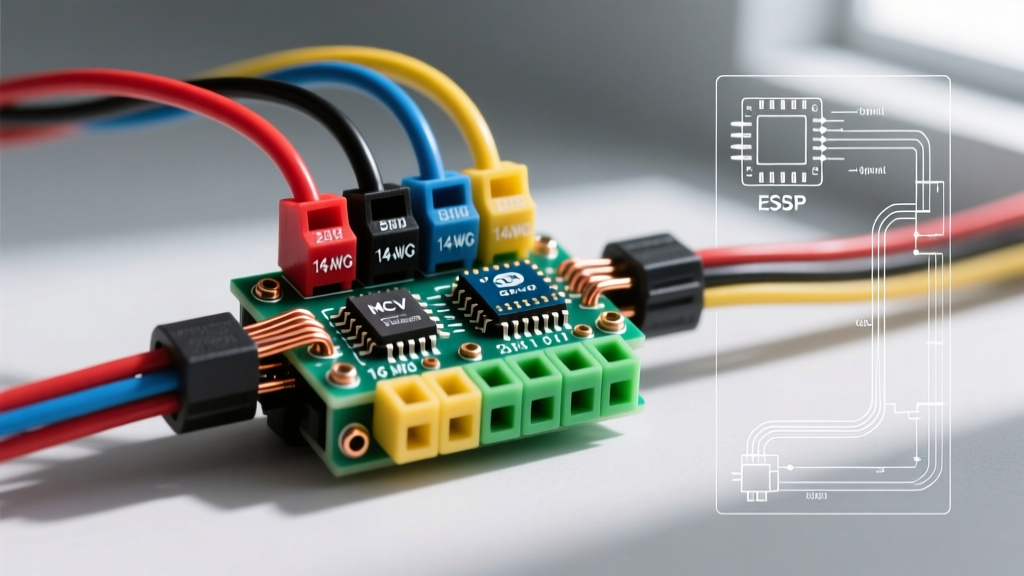

Decoding the 24v Electric Scooter Controller Wiring Diagram
Building or repairing a 24V electric scooter requires more than just connecting matching plugs. While 48V and 52V systems dominate the high-performance market, 24V architectures remain the backbone of entry-level commuters, lightweight folding scooters, and custom youth builds. As of 2026, modern 24V brushless DC (BLDC) controllers feature sophisticated field-oriented control (FOC) logic, making precise wiring more critical than ever. A standard 24v electric scooter controller wiring diagram serves as your blueprint, but without strict adherence to wire gauge (AWG) selection and standardized color codes, you risk severe voltage drops, melted XT60 connectors, or fried Hall effect sensors.
This guide provides an advanced reference for wire sizing, color mapping, and routing strategies specifically tailored for 24V DC chassis environments, ensuring your build meets both performance demands and safety standards.
Standard 24V Controller Pinout & Color Code Matrix
The industry has largely standardized around specific color sequences for BLDC motor controllers. While cheap, unbranded controllers may deviate, reputable manufacturers (such as Sabvoton, Kelly Controllers, and generic FOC clones) follow the SAE and IEC-inspired color codes for DC power and 3-phase outputs.
| Function / Circuit | Standard Wire Color | Recommended AWG (Silicone) | Typical Connector |
|---|---|---|---|
| Battery Positive (VCC) | Red | 10 AWG | XT90-S / Anderson SB50 |
| Battery Negative (GND) | Black | 10 AWG | XT90-S / Anderson SB50 |
| Motor Phase A | Yellow | 12 AWG | 4.0mm Bullet / XT60 |
| Motor Phase B | Green | 12 AWG | 4.0mm Bullet / XT60 |
| Motor Phase C | Blue | 12 AWG | 4.0mm Bullet / XT60 |
| Throttle Signal (5V) | Green or White | 22 AWG | JST-SM 3-Pin |
| Hall Sensor Signals | Yellow, Green, Blue | 24 AWG | JST-SM 5-Pin |
| Brake Cutoff (Low) | Orange / White | 22 AWG | JST-SM 2-Pin |
Expert Note: Never swap the 3-phase motor colors (Yellow, Green, Blue) to reverse motor direction. Doing so on a sensorless or Hall-sensored BLDC motor will cause the controller to misread rotor position, resulting in violent stuttering, massive current spikes, and immediate MOSFET failure. Use the controller's software or dedicated reverse-learning wire instead.
Wire Gauge Selection: The 24V Current Penalty
The most common mistake in 24V scooter builds is undersizing the main power wires. Because Power (Watts) = Voltage × Current, a 24V system must pull exactly twice the current of a 48V system to deliver the same wattage. For example, a 500W motor on a 48V system draws roughly 10.4A continuous. That same 500W motor on a 24V system draws 20.8A continuous, with starting surges easily exceeding 50A.
According to Engineering ToolBox AWG Data, standard copper wire resistance increases significantly as gauge numbers rise. For high-current DC chassis wiring, you must use stranded silicone wire (often rated for 105°C or 200°C), which has a higher ampacity than standard PVC-jacketed building wire.
Calculating Voltage Drop in 24V Chassis Wiring
In a 24V system, a 1.5V drop is a 6.25% loss of your total battery voltage, which can trigger the controller's low-voltage cutoff (LVC) prematurely under heavy acceleration. The NFPA 70 National Electrical Code recommends keeping voltage drop under 3% for optimal efficiency, though 5% is acceptable for short-run mobile DC applications.
- 10 AWG Silicone Wire: Handles up to 60A continuous in chassis wiring. Ideal for the main battery-to-controller loop on 24V systems up to 750W peak.
- 12 AWG Silicone Wire: Handles up to 40A continuous. Suitable for controller-to-motor phase wires, where the duty cycle is pulsed (PWM) rather than constant DC.
- 14 AWG Silicone Wire: Handles up to 25A. Use only for low-power accessories like 24V-to-12V DC-DC converters for headlights and horns.
Step-by-Step High-Current Routing & Crimping
Proper termination is just as critical as gauge selection. A poorly crimped 10 AWG wire will create a high-resistance joint, generating enough heat to melt the surrounding insulation.
- Strip the Silicone Jacket: Use a precision wire stripper to expose exactly 6mm to 8mm of copper strands. Do not nick the outer strands, as this reduces the effective cross-sectional area and creates a fracture point under vibration.
- Apply Heat Shrink Before Crimping: Always slide your adhesive-lined marine heat shrink onto the wire before attaching the terminal. Once crimped, you cannot add it.
- Hex Crimp, Don't Smash: For Anderson SB50 or XT90 connectors, use a dedicated hex-crimp die (like the IWISS HX-50B). Smashing the terminal with standard pliers creates voids inside the crimp barrel, leading to arcing.
- Solder the Phase Wires: For the 3-phase motor connections (Yellow, Green, Blue), solder the 4mm bullet connectors. The high-frequency PWM switching causes skin-effect current flow, and a solid solder joint minimizes impedance at the connection point.
Low-Voltage Signal Wiring: Hall Sensors & Throttles
The high-current side of your 24v electric scooter controller wiring diagram gets the most attention, but the low-voltage signal wires dictate the smoothness of your ride. Hall sensors operate on a delicate 5V logic signal. If these wires are routed parallel to the high-current phase wires, the electromagnetic interference (EMI) will induce noise, causing the controller to miscalculate the rotor position.
According to ISO 6722 Road Vehicle Cable Standards, low-tension signal cables in mobile environments require specific insulation and routing practices. For 24V scooter builds:
- Gauge: Use 22 AWG or 24 AWG stranded tinned copper. Thinner wires are more flexible, reducing the risk of internal strand breakage at the steering column hinge.
- Shielding: If your controller cable is longer than 300mm, use a shielded cable for the Hall sensor bundle. Ground the shield drain wire only at the controller end to prevent ground loops.
- Throttle Voltage: Standard hall-effect throttles output a linear 0.8V (idle) to 3.6V (full throttle) signal. Ensure your controller's 5V+ line (Red) is clean; a noisy 5V reference will cause erratic acceleration.
Critical Failure Modes & Edge Cases
Even with a perfect diagram, real-world 24V builds encounter specific edge cases that catch novice builders off guard.
The Anti-Spark Necessity
When you plug a 24V battery into a controller with large internal capacitors, the inrush current can easily exceed 100A for a fraction of a second. This causes a visible spark at the XT60 connector, which slowly pits the copper contacts, increasing resistance over time. Solution: Always use an XT90-S (Anti-Spark) connector on the main battery lead. It features a built-in resistor that pre-charges the controller capacitors before the main high-current pins make contact.
Shared Logic Ground Loops
A frequent cause of blown controller logic boards is a ground loop. The 5V logic ground (used by the throttle and display) must reference the same ground as the main power ground. If you run a separate ground wire for your DC-DC converter or display back to the battery negative terminal instead of the controller's dedicated logic ground pin, high-current motor surges will create a voltage differential. This differential can push 10V+ through the 5V logic pins, instantly frying the microcontroller.
Brake Cutoff Polarity
Most modern 24V controllers default to 'Low-Level' brake cutoffs. This means the brake signal wire (usually Orange or White) must be pulled to Ground (Black) to engage the cutoff. If your scooter's brake levers are wired as 'High-Level' (sending 5V or battery voltage when pulled), you must either swap the levers or change the controller firmware setting. Forcing a high-level signal into a low-level input pin without a current-limiting resistor will destroy the controller's input optocoupler.
Summary
Executing a flawless 24v electric scooter controller wiring diagram relies heavily on respecting the physics of low-voltage, high-current DC systems. By upsizing your main battery loops to 10 AWG silicone, strictly adhering to the Yellow-Green-Blue phase color codes, and isolating your 22 AWG Hall sensor signals from EMI sources, you ensure a reliable, efficient, and safe ride. Always verify your specific controller's pinout with a multimeter before applying main battery power, as manufacturer deviations do occur.