
Understanding the Rheem Electric Water Heater Wiring Diagram
Wiring a 240-volt electric water heater requires strict adherence to safety protocols and the National Electrical Code (NEC). Whether you are installing a standard Rheem Performance 50-gallon model (like the XE50M06ST45U1) or upgrading an older unit, understanding the Rheem electric water heater wiring diagram is critical for efficient operation and fire prevention. Unlike gas models that rely on a simple 120V igniter circuit, electric storage tanks draw substantial continuous current—typically 4,500 watts per element—demanding precise wire sizing, correct breaker selection, and proper grounding.
CRITICAL SAFETY WARNING: Never attempt to wire a 240V water heater with the main breaker ON. Use a non-contact voltage tester and a multimeter to verify zero voltage at the junction box before touching any terminals. Failure to follow Lockout/Tagout (LOTO) procedures can result in fatal electrocution.
Decoding the Diagram: Key Components
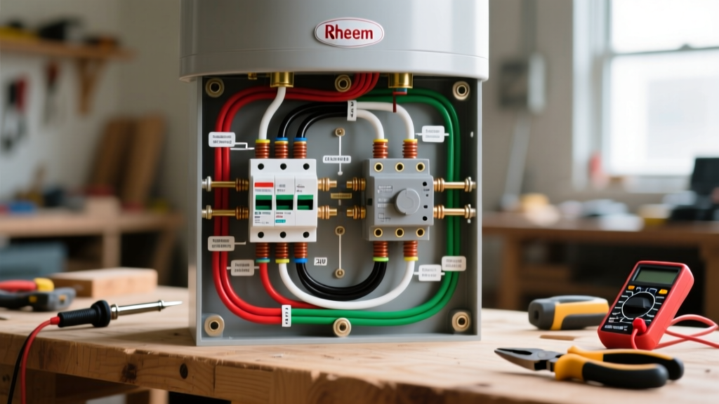
Inside the upper and lower access panels of your Rheem water heater, you will find a physical wiring schematic taped to the insulation. While it may look complex, it revolves around three main components:
- Upper and Lower Thermostats: These bi-metal switches regulate the temperature of the water. In a dual-element Rheem system, they operate non-simultaneously (only one element heats at a time) to prevent overloading a standard 30-amp residential circuit.
- Energy Cut Off (ECO) / High-Limit Switch: Integrated into the upper thermostat, this safety device physically breaks the circuit if water temperatures exceed 150°F–170°F, preventing tank explosion.
- Heating Elements: Standard Rheem tanks use 4,500W screw-in elements. The diagram shows how power routes from the upper thermostat to the upper element, and then transfers to the lower thermostat.
Pre-Wiring Checklist: Tools & Materials (2026 Pricing)
Before opening the junction box, ensure you have the correct materials. Due to fluctuating copper markets in 2026, expect to pay between $85 and $110 for a 250-foot roll of 10/2 NM-B (Romex) cable. Below is the exact bill of materials required for a standard 4,500W / 240V Rheem installation.
| Material | Specification | Estimated Cost (2026) | NEC Requirement |
|---|---|---|---|
| Circuit Breaker | 30-Amp, 240V Double-Pole | $12 - $18 | NEC 422.13 (125% continuous load rule) |
| Wiring Cable | 10/2 NM-B with Ground (Copper) | $0.40 - $0.55 / ft | NEC 310.15 (Ampacity for 10 AWG) |
| Wire Nuts | Red/Yellow Wire Connectors | $4 / pack | UL Listed for 10 AWG solid wire |
| Flex Conduit | 1/2" Liquid-Tight (if exposed) | $15 / 6ft | NEC 300.4 (Physical damage protection) |
Step-by-Step Wiring Walkthrough: 240V Dual-Element Setup
Follow these steps to execute the Rheem electric water heater wiring diagram accurately. This guide assumes you are running a new 10/2 dedicated circuit from your main electrical panel to the water heater location.
Step 1: Panel to Junction Box Routing
At the main electrical panel, install the 30-amp double-pole breaker. Strip the 10/2 NM-B cable and route it to the water heater's top junction box. Important: Leave at least 6 inches of slack inside the junction box. The white wire in a 10/2 cable is typically a neutral, but in a 240V water heater circuit, it is used as a second hot leg. You must wrap both ends of the white wire with black electrical tape or paint it black to re-identify it as a hot conductor per NEC 200.7(C).
Step 2: Junction Box Connections
- Connect the bare copper ground wire from the 10/2 cable to the green grounding screw inside the water heater's junction box. If your Rheem model has a separate chassis ground screw, run a 10 AWG bare copper jumper from the junction box ground to the chassis.
- Connect the black wire from the supply cable to the black wire on the water heater using a red or yellow wire nut.
- Connect the re-identified white (hot) wire from the supply cable to the white (or red) wire on the water heater.
- Tug each wire nut firmly to ensure a solid mechanical and electrical connection. Secure the junction box cover plate.
Step 3: Upper Thermostat and Element Wiring
Remove the insulation blanket from the upper access panel. You will see the upper thermostat with the ECO reset button.
- Line Voltage In: The black and white wires from the junction box connect to the L1 and L2 (or Line 1 / Line 2) screw terminals on the upper thermostat.
- Upper Element: Two wires will run from the upper thermostat's load terminals (often labeled T1 and T2) directly to the two screw terminals on the upper 4,500W heating element. The element is non-polarized; it does not matter which wire goes to which screw.
Step 4: Lower Thermostat and Element Wiring
The Rheem diagram routes power to the lower thermostat only after the upper tank reaches the set temperature. Locate the two wires transferring power from the upper thermostat's secondary terminals (often labeled 3 and 4 or L3/L4) down to the lower thermostat's L1 and L2 terminals.
- Connect the lower thermostat's load terminals to the two screws on the lower heating element.
- Ensure all wire connections are tight. A loose terminal on a 4,500W element will create immense resistance, leading to arcing, melted insulation, and terminal burnout.
Rheem ProTerra Hybrid (Heat Pump) Wiring Differences
If you are installing a modern Rheem ProTerra Hybrid Water Heater, the wiring diagram changes significantly. While the backup electric elements still use the standard 240V / 30A / 10 AWG configuration, the integrated heat pump compressor and smart control board require a stable voltage supply. Voltage drops below 208V can cause the compressor to short-cycle or throw an E-04 error code on the LED display. Always verify your supply voltage with a multimeter; it should read between 230V and 245V under load.
Troubleshooting Common Wiring Faults
Even with a perfect diagram, field conditions can introduce errors. Here is how to diagnose the most common Rheem wiring failures:
- Tank Trips the 30A Breaker Instantly: This is almost always a short circuit. Check for a pinched 10/2 cable behind the drywall, or inspect the elements. If an element has burned out and cracked, water may be touching the internal resistance wire, causing a dead short to ground.
- Water is Lukewarm and Runs Out Fast: The lower element is likely not receiving power. Check the wire transfer terminals between the upper and lower thermostats. Alternatively, the upper thermostat's ECO may have tripped. Press the red reset button on the upper thermostat. If it trips again immediately, replace the thermostat—do not bypass the ECO.
- Melted Wire Nuts in Junction Box: This indicates a loose connection causing high resistance and heat. Cut back the damaged wire, strip fresh insulation, and use a fresh, properly sized wire nut. Torque it until the wires twist slightly outside the nut.
NEC Compliance and Final Inspection
According to the National Fire Protection Association (NFPA), water heaters are classified as continuous loads in certain residential calculations, requiring the circuit to be rated at 125% of the appliance's maximum draw. A 4,500W element at 240V draws exactly 18.75 amps. Multiplying 18.75 by 1.25 equals 23.4 amps. Therefore, a 30-amp breaker and 10 AWG wire (rated for 30 amps) perfectly satisfy this NEC requirement. Furthermore, the U.S. Department of Energy emphasizes that proper grounding and secure physical connections are vital not just for electrical safety, but to ensure the longevity of the tank's anode rod and internal electronics.
Once all connections are verified against the Rheem diagram, replace the insulation blankets, secure the access panels with the provided screws, turn on the water supply to fill the tank completely, and only then energize the 30-amp breaker. Never energize an empty tank; the elements will dry-fire and burn out in seconds.