
The Anatomy of a 3-Wire Hall Effect Throttle
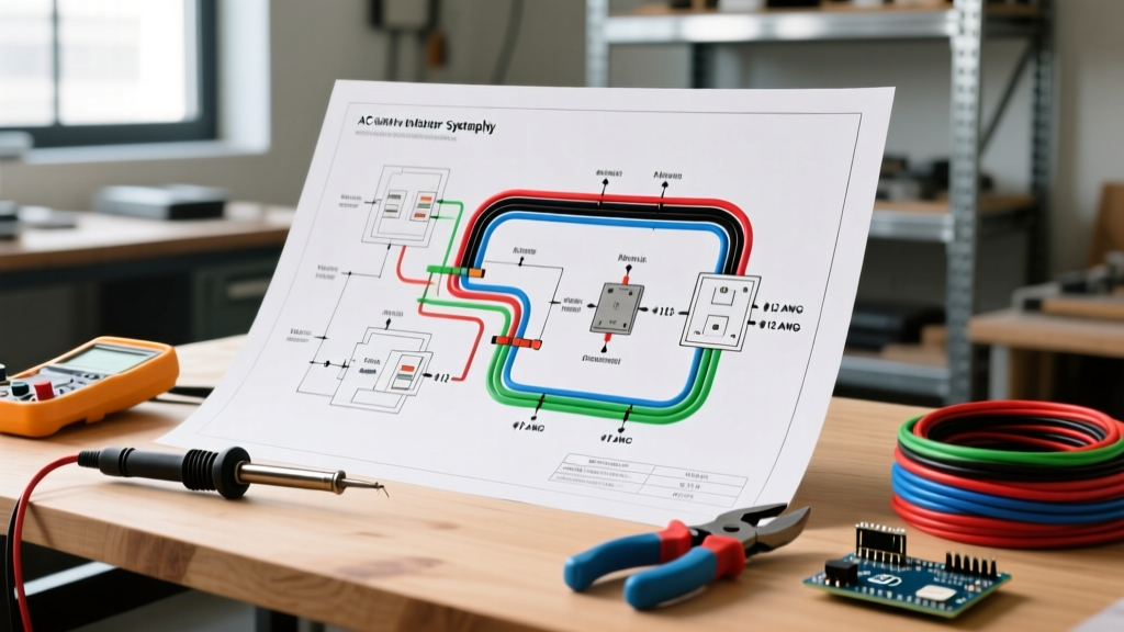
Understanding the electric bike throttle wiring diagram is a fundamental skill for any e-bike builder or technician. Unlike older potentiometer-based throttles that suffered from rapid mechanical wear and signal noise, modern e-bikes universally rely on linear Hall effect sensors (typically the SS49E or equivalent IC). These solid-state components measure changes in magnetic flux as you twist or press the throttle, outputting a clean, proportional analog voltage signal to the motor controller.
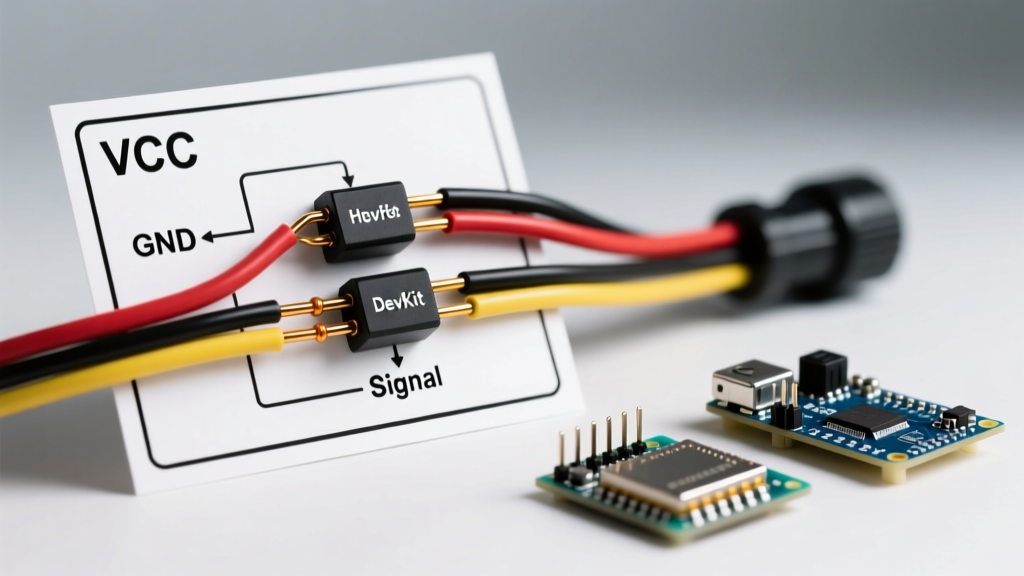
A standard e-bike throttle requires exactly three wires to function:
- VCC (+5V): Powers the internal Hall effect IC. This is supplied by the motor controller's internal 5V Low Dropout (LDO) voltage regulator.
- GND (Ground): Completes the circuit back to the controller's common ground plane.
- Signal (Output): Carries the variable voltage (typically ranging from 0.8V at rest to 4.2V at full engagement) back to the controller's microcontroller ADC pin.
Expert Warning: Never connect the throttle VCC wire directly to the main battery pack (e.g., 48V or 52V). Doing so will instantly destroy the Hall sensor and may feed high voltage back into the controller's 5V logic rail, permanently braining the MOSFET driver circuitry.
Standard Electric Bike Throttle Wiring Diagram & Pinout Table
While the internal wiring of the Hall sensor is universal, the external wire color coding can vary depending on the manufacturer. Below is the definitive pinout matrix for the most common connectors used in 2026, including the waterproof Higo Z510 and the legacy JST-SM 2.54mm pitch connectors.
| Wire Function | Standard Color (Bafang/KT) | Alternative Color (Generic/DIY) | Higo Z510 Pin Assignment | Voltage Range (DC) |
|---|---|---|---|---|
| VCC (+5V Power) | Red | Red | Pin 1 | 4.8V - 5.2V (Constant) |
| GND (Ground) | Black | White or Blue | Pin 2 | 0.0V |
| Signal (Output) | White or Green | Green or Yellow | Pin 3 | 0.8V (Rest) to 4.2V (Max) |
Note: When dealing with unbranded, direct-import throttles, always verify the pinout with a multimeter before plugging it into a premium controller. Swapping the GND and Signal wires is a common manufacturing defect that can trigger immediate over-voltage errors.
Step-by-Step Motor Controller Integration
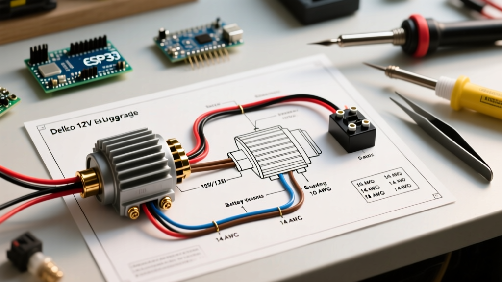
Integrating the throttle into your drivetrain requires precision. Whether you are upgrading a Bafang BBSHD mid-drive or wiring a Sabvoton 72V vector controller for a hub motor build, follow these steps to ensure signal integrity and weather resistance.
1. Verify Controller 5V Rail Health
Before connecting the throttle, power on your motor controller and use a digital multimeter (such as a Fluke 115) to back-probe the throttle port on the controller side. Set your multimeter to DC Voltage. Place the black probe on the Ground pin and the red probe on the VCC pin. You should read exactly 5.0V (±0.2V). If the reading is fluctuating or below 4.5V, your controller's internal LDO regulator is failing and must be replaced before proceeding.
2. Splicing and Waterproofing (The 2026 Standard)
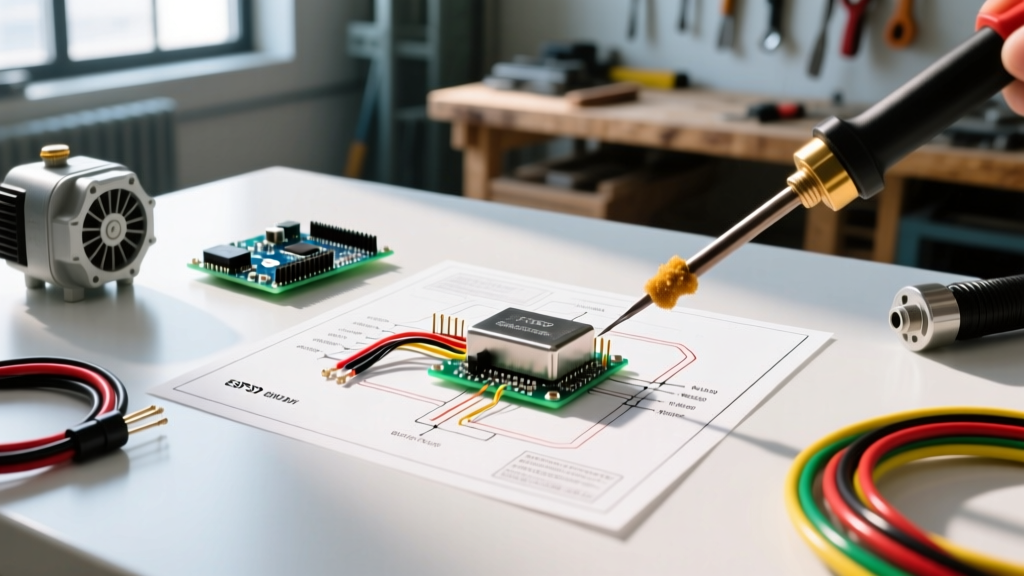
With the push for stricter micromobility safety standards, exposed solder joints and basic electrical tape are no longer acceptable for DIY or commercial builds. If you must splice a raw-wire throttle into a controller pigtail:
- Strip exactly 5mm of insulation from the 22 AWG signal wires using a precision wire stripper.
- Apply a 3:1 shrink ratio, adhesive-lined marine heat shrink tube over the wire before soldering.
- Tin both wire ends with 63/37 rosin-core solder, then join them using a Western Union splice.
- Solder the joint smoothly, ensuring no sharp spikes that could pierce the heat shrink.
- Slide the adhesive-lined heat shrink over the joint and apply heat until the internal sealant oozes from the edges, creating a 100% waterproof IP67-rated seal.
Controller Compatibility Matrix
Different motor controller ecosystems interpret the throttle signal slightly differently. Understanding these nuances is critical for proper calibration and avoiding runaway motor scenarios.
- Bafang (M620/BBSHD/BBS02): Expects a strict 0.0V to 0.8V deadband. If the resting voltage is above 0.9V, the display will throw an Error 08 (Throttle Malfunction) and disable motor assistance. Calibration is generally locked at the firmware level.
- KT Controllers (KT-V12L, etc.): Highly configurable via the LCD display (e.g., SW900 or KT-LCD10H). You can manually set the 'P11' (Throttle Start Voltage) and 'P12' (Throttle Max Voltage) parameters to match the exact output curve of your specific thumb or twist throttle.
- Sabvoton / Votol EM-Series: These high-power vector controllers require precise ADC mapping via PC software. You must perform a 'Throttle Auto-Learn' procedure in the software to map the exact minimum and maximum voltage values, ensuring smooth torque delivery without abrupt PWM spikes.
Advanced Troubleshooting & Failure Modes
When an e-bike throttle fails, it rarely just 'stops working.' It usually presents specific electrical symptoms that can be diagnosed via an electric bike throttle wiring diagram and a multimeter.
Symptom: Motor Runs at Full Power Without Throttle Input (Runaway)
Root Cause: The Signal wire is shorted to the VCC (+5V) wire, or the internal Hall sensor has failed in a 'high' state. This tells the controller that the throttle is pinned wide open.
Fix: Disconnect the throttle immediately. Measure the resistance between the Signal and VCC wires. If it reads near 0 ohms, the wiring harness is pinched and shorted. Replace the harness. If the wiring is intact, the Hall IC inside the throttle housing is destroyed and the entire throttle unit must be replaced.
Symptom: Motor Stutters or Cuts Out Mid-Ride
Root Cause: Intermittent ground connection or a failing 5V LDO on the controller. As the motor draws heavy current (e.g., 30A+ on a hill climb), voltage sag on the main battery can cause poorly designed controller LDOs to drop below 4.5V. The Hall sensor loses power for milliseconds, dropping the signal to 0V, which the controller interprets as the rider letting off the throttle.
Fix: Monitor the VCC wire at the throttle connector while the rear wheel is elevated and under load. If the 5V line dips below 4.7V under load, upgrade to a controller with a dedicated, high-amperage switching buck converter for the 5V rail.
Symptom: Throttle Dead Zone (No Power Until Half-Twist)
Root Cause: Magnet misalignment inside the throttle housing, or incorrect controller ADC mapping.
Fix: If using a programmable controller, adjust the start voltage parameter down to 0.85V. If the issue persists on a plug-and-play system, the physical return spring has weakened, or the neodymium magnet has shifted away from the SS49E sensor face. Open the housing and reseat the magnet using a dab of Loctite 495 instant adhesive.
2026 Safety Standards and Failsafe Wiring
As of 2026, compliance with UL 2849 standards for e-bike electrical systems has become a baseline requirement for commercial sales and a best practice for DIY builders. This standard heavily emphasizes the prevention of unintended acceleration and electrical fires.
To build a failsafe throttle circuit that aligns with modern safety engineering principles, you must integrate motor inhibitor (brake cutoff) circuits in parallel with your throttle logic. Modern Higo wiring harnesses include dedicated 2-pin brake cutoff connectors. When the brake lever is pulled, a simple mechanical switch pulls the controller's inhibit pin to ground (or floats it high, depending on the controller's logic), instantly disabling the PWM output to the motor MOSFETs, regardless of the throttle's signal voltage.
Furthermore, the U.S. Consumer Product Safety Commission (CPSC) strongly advises against modifying or bypassing factory throttle limiters. When wiring a custom throttle, ensure that the physical travel limit of the thumb or twist mechanism prevents the Hall sensor from exceeding 4.3V, maintaining a safe buffer below the controller's over-voltage fault threshold.
For deeper technical insights into the solid-state components powering these systems, the Texas Instruments Hall Effect Sensor Design Guide provides excellent engineering data on magnetic flux densities and linear output tolerances, which is invaluable for builders designing custom 3D-printed throttle housings for recumbent trikes or cargo e-bikes.
Summary
Mastering the electric bike throttle wiring diagram is about more than just matching red-to-red and black-to-black. It requires an understanding of analog signal processing, voltage tolerances, and waterproof integration techniques. By verifying your 5V rail, utilizing adhesive-lined heat shrink, and properly mapping your controller's ADC parameters, you ensure a responsive, safe, and reliable ride for thousands of miles.