
The Critical Importance of Alternator Wiring Safety
Vehicle electrical fires remain a leading cause of roadside emergencies, and improper charging system wiring is a frequent culprit. As modern vehicles integrate high-draw ADAS sensors, start-stop modules, and auxiliary 48V systems, the baseline output of factory alternators has surged. In 2026, it is common to see 150A to 250A alternators even on standard internal combustion engine (ICE) platforms. When upgrading or repairing these systems, relying on a generic wiring diagram for car alternator setups without considering SAE (Society of Automotive Engineers) code compliance and overcurrent protection is a severe safety hazard.
According to data from the National Highway Traffic Safety Administration (NHTSA), electrical failures and short circuits account for a significant percentage of vehicle fires. This guide provides a comprehensive, safety-first approach to alternator wiring, focusing on wire gauge selection, insulation standards, and precise fusing protocols to protect your vehicle and its occupants.
Decoding the Terminals: 1-Wire vs. 3-Wire Alternator Diagrams
Before selecting wire gauges, you must identify your alternator's internal regulator topology. Most modern replacements (such as the Denso 10SI or Bosch AL7780X series) utilize a 3-wire or 4-wire harness to ensure precise voltage regulation.
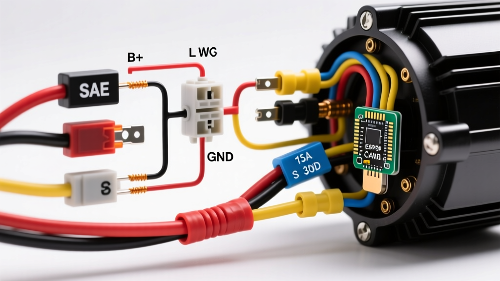
- B+ (Battery Output): The main high-current output terminal. This carries the full amperage load to the battery and vehicle bus.
- IG (Ignition): A switched 12V source that wakes the internal regulator when the key is in the 'ON' position.
- S (Sense): The most critical wire for battery health. It reads the actual voltage at the battery post. If this wire is damaged or routed poorly, the alternator will overcompensate for voltage drop, potentially boiling the battery electrolyte.
- L (Lamp): Connects to the dashboard warning light and provides the initial excitation current to the rotor.
Safety Warning: Never use a 1-wire 'self-exciting' alternator diagram for high-output applications (100A+). Bypassing the sense wire forces the regulator to read voltage at the B+ terminal, ignoring the voltage drop across the main harness, which leads to chronic undercharging or dangerous overcharging at the battery.
SAE Code Compliance: Wire Gauge and Insulation Standards
Standard PVC-insulated wire found in big-box hardware stores is entirely unsuitable for under-hood alternator wiring. SAE standard J1128 mandates the use of cross-linked polyethylene (XLPE) insulation, commonly designated as GXL, TXL, or SXL. These insulations are rated for continuous operation at 125°C to 150°C, resisting the extreme radiant heat of exhaust manifolds and engine blocks.
When calculating the required American Wire Gauge (AWG), you must account for both the maximum amperage and the physical length of the wire run (from the alternator B+ post to the main battery positive post). The NEC and SAE recommend keeping voltage drop below 3% (approx. 0.36V on a 12V system).
AWG Sizing Chart for Alternator B+ Output (GXL/TXL Wire)
| Alternator Max Output | Run Length (Under 4 ft) | Run Length (4 - 8 ft) | Run Length (8 - 12 ft) |
|---|---|---|---|
| 60A - 80A | 8 AWG | 6 AWG | 4 AWG |
| 90A - 120A | 6 AWG | 4 AWG | 2 AWG |
| 130A - 160A | 4 AWG | 2 AWG | 1/0 AWG |
| 170A - 250A | 2 AWG | 1/0 AWG | 2/0 AWG |
Note: Always size the wire based on the alternator's maximum rated output, not the vehicle's typical cruising draw. A 150A alternator can dump 150A into a deeply depleted battery immediately upon startup.
Overcurrent Protection: The 18-Inch Rule and Fuse Selection
The most catastrophic failure mode in alternator wiring is a short circuit between the B+ terminal and the chassis ground. Because the B+ wire is connected directly to the battery, a short will draw thousands of amps, instantly melting the wire harness and igniting surrounding components. Overcurrent protection is non-negotiable.
Industry leaders like Blue Sea Systems and marine ABYC standards dictate that the main overcurrent fuse must be installed within 18 inches (45 cm) of the battery positive terminal. If the wire shorts anywhere after the fuse, the fuse blows, protecting the entire harness.
Selecting the Right Fuse Technology
Standard automotive blade fuses (ATO/ATC) max out at 40A, and Maxi fuses at 80A. For modern high-output alternators, you must use high-amperage, high-interrupt-capacity fuses:
- ANL Fuses (e.g., Bussmann ANN series): Ideal for 100A to 250A applications. They feature a silver-plated copper element and a high interrupt capacity, meaning they can safely stop a massive short-circuit current without shattering.
- MEGA / AMI Fuses (e.g., Littelfuse MEGA): A more compact, bolt-down alternative to ANL, commonly used in OEM 2026 vehicle architectures. Rated up to 250A at 32V DC.
- Class T Fuses: The gold standard for severe-duty and marine applications. They offer the fastest trip times and highest interrupt ratings (up to 20,000 amps), essential for lithium-ion battery banks paired with high-output alternators.
Fuse Sizing Rule: Size the fuse to protect the wire, not the alternator. If you are using 2 AWG GXL wire (rated for ~210A), use a 175A or 200A ANL fuse. This ensures the fuse blows before the wire insulation reaches its melting point.
Grounding and Sense Wire Routing Protocols
A wiring diagram for car alternator compliance is incomplete without addressing the ground path. The alternator case grounds through its mounting brackets to the engine block. Over time, oil, dirt, and galvanic corrosion increase the resistance of this path.
- Supplemental Ground Strap: Always install a dedicated 4 AWG or 6 AWG flexible braided copper ground strap directly from an unused alternator casing bolt to the vehicle chassis or battery negative terminal.
- Sense Wire Routing: The Sense (S) wire must be routed away from high-voltage ignition coils and EFI injectors to prevent electromagnetic interference (EMI). Use a 14 AWG wire fused at 5A, terminating directly at the battery positive post or the main distribution busbar.
Step-by-Step Safe Installation Protocol
Follow this precise sequence to ensure mechanical and electrical integrity:
- Disconnect Power: Remove the negative battery terminal first to eliminate ground-loop risks.
- Mount the Fuse Holder: Secure the ANL/MEGA fuse holder within 18 inches of the battery positive post. Leave the fuse out during installation.
- Crimp and Seal: Use a hex-crimp tool (not a standard plier crimper) for heavy-gauge ring terminals. Apply dual-wall adhesive-lined heat shrink (3:1 shrink ratio) to prevent moisture ingress and copper oxidation.
- Torque the B+ Nut: The B+ terminal nut is typically M8 or M10. Use a torque wrench to tighten to the manufacturer's specification (usually 8 to 12 Nm). Overtightening will strip the aluminum threads on the alternator casing; undertightening causes micro-arcing and localized melting.
- Install the Fuse & Test: Insert the fuse, reconnect the battery negative, and start the engine. Use a digital multimeter to verify voltage at the battery posts. It should read between 13.8V and 14.4V at 2,000 RPM with accessories off.
Summary of SAE Best Practices
Adhering to SAE International guidelines for wire insulation and circuit protection transforms a risky DIY project into a reliable, OEM-grade repair. By utilizing GXL cross-linked wiring, calculating voltage drop over distance, and enforcing the 18-inch fusing rule, you ensure that your vehicle's charging system can handle the electrical demands of modern automotive technology without compromising safety.