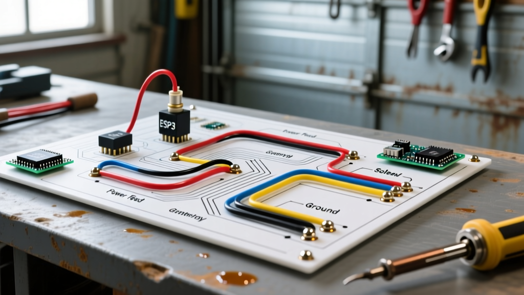

Decoding the 3-Plug System: Your Wiring Diagram for a Western Plow
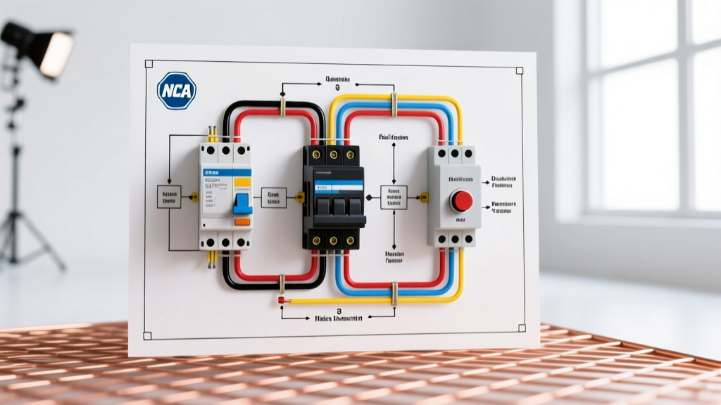
Installing a snow plow electrical system requires precision, patience, and a clear understanding of the manufacturer's schematics. When interpreting a wiring diagram for a western plow, particularly the industry-standard UltraMount 2 or Multiplex systems, you are typically looking at a 3-plug configuration. This setup isolates high-amperage hydraulic power from sensitive low-voltage control and lighting circuits, preventing voltage drops and electromagnetic interference.
Before cutting a single zip tie, you must understand the three distinct harnesses detailed in the official Western Plows literature database:
- 2-Pin Power Plug: Carries heavy current (up to 150A) directly from the vehicle battery to the plow motor solenoid.
- 4-Pin Control Plug: Transmits low-voltage signals from the cab controller to the Vehicle Control Module (VCM) to trigger hydraulic valves.
- 11-Pin Lighting Plug: Routes headlamp, turn signal, and marker light circuits from the truck’s OEM lighting harness to the plow lights.
Expert Tip: Never attempt to splice the 11-pin lighting harness into the truck's wiring without the OEM-specific headlamp adapter (e.g., HB4/HB5 or H13 adapters). Modern trucks use CAN-bus or PWM (Pulse Width Modulation) lighting circuits; direct splicing will trigger dashboard error codes and disable your headlights.
Pre-Installation Checklist and Specialized Tools
A standard socket set won't cut it for a professional-grade plow wiring job. To ensure your connections match the specifications in the wiring diagram for a western plow, gather the following specific tools and materials:
- Wire Strippers: Klein Tools 11055 (handles 10-20 AWG) and a heavy-duty cutter for 2 AWG battery cable.
- Crimpers: Hydraulic or heavy ratcheting crimper for 2 AWG ring terminals (e.g., Knoweasy or Titan).
- Dielectric Grease: Permatex 22058 (essential for all multi-pin plugs to prevent winter moisture corrosion).
- Heat Shrink: 3M 1/2-inch and 1/4-inch adhesive-lined heat shrink tubing (provides a waterproof seal over crimps).
- Circuit Protection: 150-Amp manual reset circuit breaker (Western part #53714 or equivalent Bussmann).
Step-by-Step Wiring Walkthrough
Step 1: Main Power and Ground Routing (2-Pin Harness)
The most critical part of the wiring diagram for a western plow is the high-current motor circuit. A poor connection here will result in sluggish hydraulic performance or a melted harness.
- Disconnect the Battery: Always remove the negative terminal first.
- Install the Circuit Breaker: Mount the 150A breaker within 18 inches of the positive battery terminal. This is a strict requirement to protect the short run of unprotected wire.
- Run the 2 AWG Positive Cable: Route the red 2 AWG cable from the breaker to the plow solenoid's large "B" (Battery) terminal. Keep this cable away from the exhaust manifold and sharp frame edges. Use split-loom tubing for the entire run.
- Establish the Ground: Do not rely on the plow's pivot points for grounding. Run a dedicated 2 AWG black ground cable from the plow motor's ground stud directly to the vehicle's clean, bare frame or the negative battery terminal. Sand the frame contact point down to bare metal and apply a coating of anti-corrosion spray.
Step 2: Solenoid and Motor Power Integration
The solenoid acts as a heavy-duty relay, allowing a small control current to switch the massive motor current.
- Connect the 2 AWG cable from the motor to the solenoid's "M" (Motor) terminal.
- Connect the small red trigger wire (usually 14 AWG) from the 4-pin control harness to the solenoid's "S" (Switch) terminal.
- Ground the solenoid bracket to the vehicle frame. If using an isolated-ground solenoid (like the Trombetta 70-111224), ensure the small black ground wire is connected to a clean chassis ground.
Step 3: Vehicle Control Module (VCM) and Cab Wiring
The VCM is the brain of the Multiplex and UltraMount systems. It interprets joystick inputs and fires the hydraulic valve coils.
- Mount the VCM in the engine bay, preferably on the firewall or inner fender, away from extreme heat.
- Route the 4-pin control cable through the firewall using an existing rubber grommet. Never drill a new hole without installing a rubber grommet and sealing it with silicone.
- Connect the cab-side harness to the joystick or handheld controller. Ensure the red ignition wire is tapped into a true 12V ignition-switched source (verify with a multimeter; it should read 0V when the key is off and 12V+ when running).
Step 4: Lighting Harness and Headlamp Integration (11-Pin)
Lighting is where most DIY installers make mistakes. Follow the lighting section of the wiring diagram for a western plow meticulously.
- Plug the truck-side 11-pin harness into the OEM headlamp adapters. For example, if your truck uses H13 bulbs, use the Western H13 adapter harness.
- Route the harness to the front of the grille, securing it with UV-resistant zip ties every 12 inches.
- Apply a generous amount of Permatex dielectric grease to the 11-pin plug before mating it to the plow-side receptacle. Twist the locking ring until it clicks.
Wire Gauge and Amperage Reference Chart
Adhering to the correct wire gauge is non-negotiable to prevent voltage drop and fire hazards. Use this reference table when verifying your harness against the wiring diagram for a western plow.
| Circuit Function | Wire Gauge | Max Amperage | Protection Rating | Typical Wire Color |
|---|---|---|---|---|
| Plow Motor Power | 2 AWG | 150A (Peak) | 150A Breaker | Red / Black |
| Solenoid Trigger | 14 AWG | 10A | 15A Inline Fuse | Red (w/ tracer) |
| VCM Power Feed | 12 AWG | 20A | 20A Inline Fuse | Red |
| Hydraulic Valve Coils | 16 AWG | 5A per coil | Protected by VCM | Various (Brown, Blue, etc.) |
| Headlamp Power | 14 AWG | 10A per lamp | OEM Fuses | Red / Black |
| Turn Signals / Markers | 16 AWG | 4A | OEM Fuses | Yellow / Green / Brown |
Troubleshooting Common Diagram Misinterpretations
Even experienced mechanics can misread a schematic. If your plow isn't responding after following the wiring diagram for a western plow, check these specific failure modes before replacing expensive components.
1. The "Click but No Movement" Solenoid Fault
If you hear the solenoid click but the motor doesn't spin, the control circuit is working, but the load circuit is failing. This is almost always caused by:
- Corroded or loose 2 AWG ring terminals at the battery or breaker.
- A failing solenoid. Test the large terminals with a multimeter while pressing the control button. If you read 12V+ on the "B" terminal but 0V on the "M" terminal when engaged, the solenoid contacts are burnt. Replace it with a continuous-duty model (approx. $45 to $80).
2. Plow Lights Work, But Truck Lights Stay On
This is a classic isolation relay failure. The wiring diagram for a western plow utilizes an isolation module to cut power to the truck headlights when the plow is plugged in. If the truck lights remain on:
- Check the ground wire on the isolation module. A floating ground will prevent the internal relays from switching.
- Inspect the OEM headlamp adapter pins. Bent pins in the H13 or HB5 adapters will fail to trigger the module's sensing circuit.
3. Intermittent Controller Shutdowns
If the cab controller randomly powers off while plowing, you likely have a voltage drop on the ignition sense wire. Do not tap the ignition wire into high-draw circuits like the wiper motor or HVAC blower. Use a multimeter to find a dedicated ignition circuit in the fuse box, and use a proper add-a-circuit fuse tap rather than a scotch lock connector, which is notorious for vibrating loose and causing intermittent power loss.
Final Verification and Safety Checks
Once all connections are made according to the wiring diagram for a western plow, perform a final continuity and voltage drop test. With the engine running, measure the voltage at the plow motor terminals while actuating the angle and lift functions. The voltage should not drop below 11.5V. If it drops to 10V or lower, you have excessive resistance in your 2 AWG power or ground cables.
Finally, secure all harnesses away from moving steering components and the hydraulic lift cylinder. Use Western-approved mounting brackets for the grille-side plugs to prevent them from dangling and getting ripped out during highway transit. For further technical bulletins and updated schematics, always refer to the Western Plows official support portal to ensure your specific model year is covered.