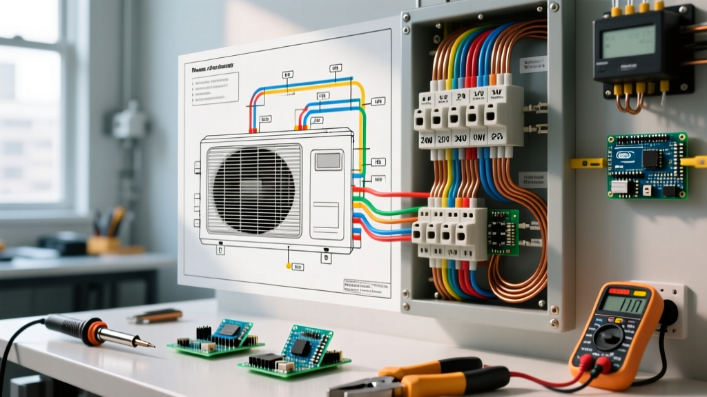

Decoding the Wiring Diagram for Home Air Conditioner Systems
Installing or servicing a residential split-system air conditioner requires a precise understanding of both high-voltage power routing and low-voltage control circuits. As HVAC technology advances in 2026, with the widespread adoption of SEER2-compliant variable-speed compressors and smart communicating thermostats, the wiring diagram for home air conditioner units has become more complex. Whether you are wiring a standard single-stage 3-ton unit like the Trane XR15 or a multi-stage Carrier Infinity system, misinterpreting the schematic can lead to blown control board fuses, compressor burnout, or severe electrical hazards.
This comprehensive appliance wiring tutorial breaks down the exact schematics, wire gauge requirements, and National Electrical Code (NEC) mandates you need to safely terminate a residential split-system AC.
Anatomy of a Split-System AC Schematic
A standard home air conditioner wiring diagram is divided into two primary zones: the high-voltage power circuit (240V) and the low-voltage control circuit (24V). The schematic provided on the inside of the outdoor condenser's access panel acts as your master roadmap.
High-Voltage Power Routing (240V)
The 240V circuit originates at your main electrical panel, travels through a dedicated double-pole circuit breaker, and exits to an exterior disconnect box. From the disconnect, a flexible liquid-tight whip feeds power directly into the outdoor condenser unit. Inside the condenser, the 240V lines (L1 and L2) terminate on the main contactor relay. The contactor acts as a heavy-duty switch; when the 24V control signal energizes the contactor coil, the magnetic field pulls the contacts down, sending 240V to the compressor and the condenser fan motor.
According to the National Fire Protection Association (NFPA 70), Article 440 governs the specific wiring rules for air-conditioning and refrigerating equipment. A critical 2026 NEC update reinforces the use of calibrated torque screwdrivers for all terminal connections to prevent micro-arcing and subsequent fires.
Wire Gauge and Breaker Sizing Matrix
Never guess your wire size. Always refer to the unit's data plate for the Minimum Circuit Ampacity (MCA) and Maximum Overcurrent Protection (MOP). Below is the standard matrix for residential copper THHN/THWN-2 wiring in 2026:
| AC Tonnage | Typical MCA | Typical MOP | Recommended Copper Wire | Breaker Size | Approx. Material Cost (2026) |
|---|---|---|---|---|---|
| 1.5 - 2.0 Ton | 14A | 20A | 12 AWG | 20A Double-Pole | $0.85 / ft |
| 2.5 - 3.0 Ton | 22A | 30A | 10 AWG | 30A Double-Pole | $1.15 / ft |
| 4.0 - 5.0 Ton | 32A | 40A | 8 AWG | 40A Double-Pole | $1.65 / ft |
Low-Voltage Control Circuit (24V)
The control circuit is the 'brain' of the operation. It utilizes an 18-gauge, multi-strand thermostat wire (typically 18/5 or 18/8). The 24V alternating current is generated by a step-down transformer located in the indoor air handler or gas furnace. When the thermostat calls for cooling, it closes the circuit between the R (Power) and Y (Compressor) terminals, sending 24V down to the outdoor unit's contactor coil.
The Dual Run Capacitor: A Wiring Critical Point
One of the most common areas where DIYers and junior technicians make errors on the wiring diagram for home air conditioner systems is the dual run capacitor. This cylindrical component provides the phase shift necessary to keep the single-phase compressor and fan motors running efficiently.
- C (Common): Receives the L2 (or L1, depending on the schematic) 240V leg directly from the contactor.
- HERM (Hermetic): Feeds the start winding of the compressor.
- FAN: Feeds the start winding of the outdoor condenser fan motor.
Expert Tip: Always use a multimeter with a microfarad (µF) setting to test the capacitor before wiring. A 45/5 µF capacitor should read within 6% of its rated capacity. If it reads below 42 µF, replace it before terminating the wires, or the compressor will overheat and trip its internal thermal overload.
Step-by-Step Installation & Termination Guide
Follow this sequence to ensure a safe, code-compliant installation. The U.S. Department of Energy emphasizes that proper electrical termination directly impacts the long-term SEER2 efficiency rating of the equipment.
- Mount the Disconnect Box: Install a non-fused (or fused, if MOP requires) 60A-rated disconnect box within sight of the outdoor unit, no more than 50 feet away (NEC Article 440.14).
- Pull the High-Voltage Whip: Use 1/2-inch liquid-tight flexible metallic conduit (LFMC) for the final 6 feet. Strip the THHN wires, ensuring no more than 3/4-inch of bare copper is exposed to prevent shorting against the condenser chassis.
- Terminate the Contactor: Connect L1 and L2 to the top lugs of the contactor. Use a calibrated torque screwdriver set to the manufacturer's specification (usually 20-25 in-lbs for 10 AWG wire) to meet NEC 110.14(D) requirements.
- Wire the Control Circuit: Route the 18/8 thermostat wire through a separate, dedicated knockout hole to prevent high-voltage electromagnetic interference (EMI) from disrupting smart thermostat signals. Connect the 'Y' wire to the contactor coil and the 'C' wire to the common side of the coil.
- Secure the Crankcase Heater: If your climate experiences freezing winters, wire the crankcase heater directly to the line-side of the contactor. This ensures the heater warms the compressor oil even when the thermostat is not calling for cooling.
Common Wiring Faults and Diagnostic Tips
Even with a perfect wiring diagram for home air conditioner units, field conditions can introduce faults. Here is how to troubleshoot the most frequent electrical failures:
1. The Blown 3-Amp or 5-Amp Control Board Fuse
If the indoor air handler's control board blows its automotive-style ATC fuse every time the AC kicks on, you have a dead short in the low-voltage wiring. This is almost always caused by the 'Y' or 'G' (fan) wire rubbing against a sharp piece of sheet metal on the condenser cabinet, grounding out the 24V circuit. Inspect the entire run of the 18-gauge wire and use grommets on all metal penetrations.
2. Contactor Chatter or Humming
If the outdoor contactor vibrates loudly and fails to pull in completely, the 24V control signal is weak. This can be caused by undersized thermostat wire (e.g., using 20 AWG instead of 18 AWG on a run longer than 50 feet), resulting in excessive voltage drop. Upgrade to 18/5 wire or install a hard-start relay kit.
3. Reversed Compressor Leads (Single-Phase vs. Three-Phase)
For standard residential single-phase 240V systems, swapping the L1 and L2 leads on the compressor terminals will not damage the unit, as single-phase motors alternate direction naturally via the capacitor's phase shift. However, if you are wiring a light-commercial 3-phase unit in a large residential estate, reversing two of the three legs will cause the scroll compressor to run backward, resulting in zero cooling and catastrophic mechanical failure within minutes.
CRITICAL SAFETY WARNING: Always lock out and tag out (LOTO) the main breaker and the exterior disconnect before opening the condenser panel. Capacitors can hold a lethal 240V+ charge long after power is removed. Use a 20,000-ohm, 2-watt resistor to safely bleed the capacitor terminals before touching any wiring, and verify zero energy state with a CAT III rated digital multimeter.
Final Code Compliance Checks for 2026
Before energizing the system, verify that a 120V, 15A or 20A GFCI-protected service receptacle is installed within 25 feet of the outdoor condenser. This is mandated by NEC Article 210.63 to allow service technicians to plug in vacuum pumps and recovery machines safely. Furthermore, ensure all low-voltage control wires are secured with UV-rated zip ties and kept at least 2 inches away from the high-voltage compressor lines to prevent insulation degradation over time.
Mastering the wiring diagram for home air conditioner systems bridges the gap between mechanical cooling theory and safe, reliable electrical execution. Always defer to the specific schematic located on your unit's access panel, as manufacturer revisions can alter terminal designations between model years. For further certification and training standards, consult the Air-Conditioning, Heating, and Refrigeration Institute (AHRI).