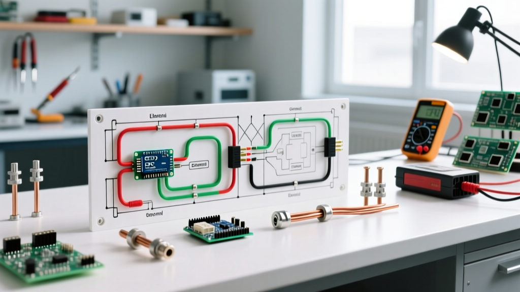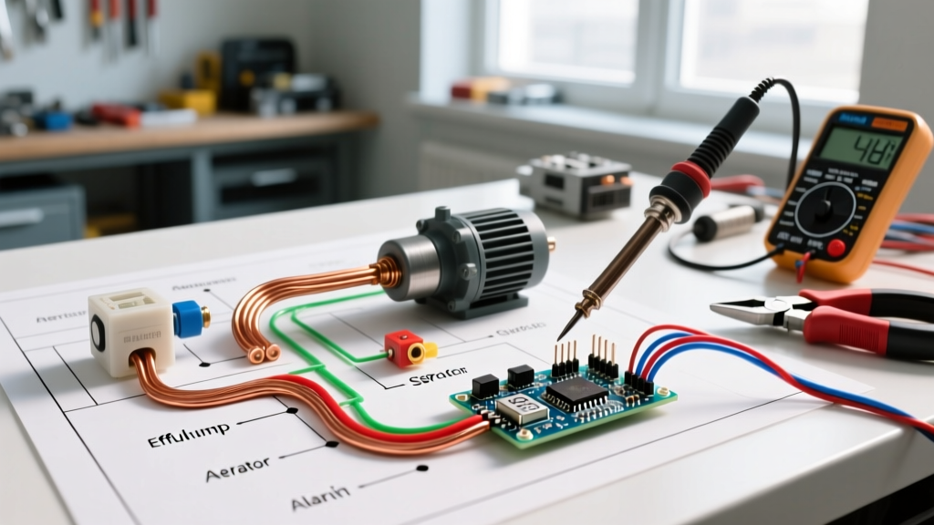

Understanding the Wiring Diagram for Septic System Motors
Wiring a septic system goes far beyond simply plugging in a sump pump. Modern residential and commercial septic setups rely on a synchronized network of fractional-horsepower motors, effluent pumps, aerobic aerators, and multi-stage float switches. A flawed wiring diagram for septic system configurations can lead to catastrophic motor burnouts, sewage backups, or dangerous electrical faults in damp environments. In 2026, with stricter local amendments to the National Electrical Code (NEC) regarding outdoor moisture and ground-fault protection, understanding the exact terminal logic, wire gauge requirements, and overload protections is critical for any DIYer or electrical apprentice.
This comprehensive motor wiring tutorial breaks down the control panel logic, pump motor specifications, and the exact wiring sequences required to build a safe, code-compliant septic electrical system.
Core Septic Motors and Pump Specifications
Before tracing the wiring diagram, you must identify the specific motor types in your system. Septic motors generally fall into three categories: sewage ejector pumps (handling solids), effluent pumps (handling greywater), and aerator motors (for Aerobic Treatment Units or ATUs). Below is a comparison of industry-standard models and their electrical requirements.
| Component Type | Example Model | Voltage / Phase | FLA (Full Load Amps) | LRA (Locked Rotor Amps) |
|---|---|---|---|---|
| Sewage Ejector Pump | Zoeller M53 (1/2 HP) | 120V / 1-Phase | 9.4 A | 28.0 A |
| Effluent Pump | Liberty Pumps LE51A (1/2 HP) | 120V / 1-Phase | 10.0 A | 32.0 A |
| Aerator Motor (ATU) | Septic Air HAP80 (Linear) | 120V / 1-Phase | 1.6 A | N/A (Diaphragm) |
| High-Head Effluent | Franklin Electric 1HP | 240V / 1-Phase | 8.2 A | 45.0 A |
Note: Always reference the specific nameplate data on your motor. Locked Rotor Amps (LRA) dictate the sizing of your circuit breaker and motor overload relays in the control panel.
The Master Control Panel Wiring Sequence
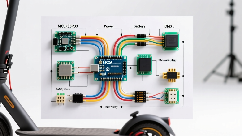
A dedicated septic control panel acts as the brain of the system. It houses the contactors, overload relays, and alarm circuits. According to the NFPA 70 (NEC), motors must have dedicated disconnects and overload protection. Here is the step-by-step wiring flow for a standard 120V duplex pump system with a high-water alarm.
1. Incoming Power and Disconnect
Run 10/3 UF-B (Underground Feeder) cable from the main service panel to the septic control panel. The 10 AWG wire ensures minimal voltage drop over the typical 50-to-100-foot trench run. Terminate the black (L1) and white (L2/Neutral) wires on the main 30A 2-pole breaker inside the septic panel. Terminate the bare copper to the dedicated ground bus bar.
2. Wiring the Motor Contactors
Unlike direct-plug setups, hardwired panels use contactors to handle the high inrush current of the pump motors.
- Line Side: Wire L1 and Neutral from the breaker to the top terminals of the contactor.
- Load Side: Wire the bottom terminals of the contactor to the pump motor leads (Black to L1, White to Neutral).
- Coil Circuit: The contactor coil (usually 120V) is wired in series with your float switches. When the float rises, it completes the 120V circuit to the coil, pulling the contactor closed and starting the motor.
3. Integrating the Alarm Circuit
The alarm circuit must be independent of the pump circuits. If a pump fails, the alarm must still sound. Wire a dedicated 15A breaker for the alarm module. Connect the audio-visual alarm (e.g., a 120V horn/strobe combo) to the alarm relay's Normally Open (NO) contacts. The high-level alarm float switch provides the trigger signal to the relay coil.
Float Switch Logic: Piggyback vs. Panel Wiring
Float switches dictate when your septic motors turn on and off. There are two primary wiring methods, and choosing the wrong one is a leading cause of motor failure.
Pro Tip: Never wire a mechanical float switch directly in series with a high-horsepower septic motor. The inrush current (LRA) will arc and weld the internal contacts of the float switch shut within weeks, causing the pump to run continuously until the motor burns out. Always use a control panel with contactors or a dedicated pump relay.
Piggyback Plugs (Direct Wire Pumps)
For simple, single-pump systems without a control panel, use a piggyback float switch. The pump's power cord plugs into the back of the float switch cord, and the float switch plugs into a dedicated 120V GFCI-protected receptacle.
- Pump-On Float: Normally Open (NO). Closes when water rises.
- Pump-Off Float: Normally Closed (NC). Opens when water drops to the minimum safe level, preventing dry-running.
Control Panel Low-Voltage Floats
In advanced panels, floats are wired to a low-voltage (24VAC) terminal block. This keeps 120V/240V line voltage out of the wet septic tank environment. The 24V signal triggers an internal relay, which then engages the main motor contactor. This is the safest and most reliable method recommended by manufacturers like Zoeller Pump Company.
Wire Sizing and Voltage Drop Calculations
Septic tanks are often located at the far edge of a property. Voltage drop is a silent killer of septic motors. If a 120V motor receives less than 108V (a 10% drop), it will draw excess amperage, overheat, and trip its internal thermal overload repeatedly.
The 3% Rule: NEC recommends a maximum 3% voltage drop for branch circuits. For a 120V circuit, this means a maximum drop of 3.6V.
| Distance from Panel | 1/2 HP (120V, 10A) | 1 HP (240V, 8A) |
|---|---|---|
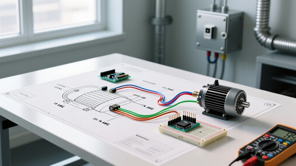
| Up to 50 Feet | 12 AWG Copper | 14 AWG Copper |
| 50 to 100 Feet | 10 AWG Copper | 12 AWG Copper |
| 100 to 150 Feet | 8 AWG Copper | 10 AWG Copper |
NEC Code Requirements and Grounding
Wiring a septic system intersects with several critical NEC articles. As of the latest code cycles, the EPA's guidelines on septic system maintenance heavily emphasize electrical safety to prevent shock hazards in saturated soil.
- NEC Article 430 (Motors): Requires motor overload protection sized at 115% to 125% of the motor's Full Load Amps (FLA). Most modern submersible septic pumps have built-in thermal overloads, but the control panel must still feature appropriately sized fuses or breakers for short-circuit protection.
- NEC Article 250 (Grounding): The septic tank's metal components (if any), the pump housing, and the control panel enclosure must be bonded to an equipment grounding conductor (EGC). Never rely on the earth or a ground rod alone to clear a fault in a wet environment.
- GFCI Protection: While NEC requires GFCI protection for outdoor 120V receptacles, hardwired sewage ejector pumps are often exempt from GFCI requirements in specific local jurisdictions to prevent nuisance tripping, which could result in a raw sewage backup. Always consult your local Authority Having Jurisdiction (AHJ) regarding GFCI breakers for hardwired septic motors.
Troubleshooting Common Motor and Wiring Failures
Even with a perfect wiring diagram for septic system layouts, environmental factors cause failures. Here is how to diagnose the most common issues using a digital multimeter (DMM).
1. The Start Capacitor Failure
Single-phase septic motors use a start capacitor to generate the phase shift needed for initial torque. If the pump hums but won't spin, the capacitor is likely dead.
- Test: Disconnect power, discharge the capacitor with a 20k-ohm resistor, and measure with a DMM set to microfarads (µF). A healthy 1/2 HP pump capacitor typically reads between 130µF and 156µF. If it reads below 100µF or shows an open circuit (OL), replace it with an identical voltage/µF rated unit.
2. Moisture Ingress in the Cable Seal
Submersible pumps feature a resin-filled cable seal where the power cord enters the motor housing. If the cord is pulled or bent sharply during installation, the seal cracks. Moisture enters, causing a ground fault.
- Test: Set your multimeter to Megohms (or use a dedicated Megger). Test between the L1 motor lead and the ground wire. A reading below 2 Megohms indicates moisture inside the motor housing. The pump must be pulled and replaced; it cannot be safely repaired in the field.
3. Aerobic Aerator Motor Burnout
Aerator motors (like linear diaphragm or rotary vane types) run 24/7. They are highly susceptible to voltage spikes and lightning strikes due to their constant connection. Always install a whole-house surge protector or a dedicated point-of-use surge suppression module (rated for at least 50kA) inside the septic control panel to protect the aerator's sensitive internal windings and diaphragms.
Final Commissioning Steps
Once all wiring is terminated and torque-checked:
- Verify all ground connections with a continuity tester.
- Turn on the main disconnect and measure line voltage at the contactor load side (should be within 2% of nominal).
- Manually lift the pump-on float switch to engage the contactor. Verify the pump draws amperage within the FLA rating on the nameplate using a clamp meter.
- Lift the high-water alarm float to ensure the horn and strobe activate independently of the pump circuit.