
Engineering a Fire-Safe Radiator Fan Electric Fan Relay Wiring Diagram
As automotive thermal management systems grow more complex in 2026—especially with the integration of high-output alternators and 48V mild-hybrid architectures—the foundational 12V auxiliary cooling circuit remains a critical point of failure. Executing a flawless radiator fan electric fan relay wiring diagram is not merely about making the fan spin; it is about managing high inductive loads, preventing voltage drop, and eliminating fire hazards. Direct-wiring a 20-amp electric fan to a dashboard toggle switch or a low-amperage thermal sensor is a severe code violation and a guaranteed path to melted harnesses. This guide details the exact hardware, wire gauges, and safety protocols required to build a robust, SAE-compliant relay circuit.
Core Hardware Selection: Beyond the Auto Parts Store Bin
The most common failure mode in DIY fan wiring is the use of substandard relays and residential-grade wire. To ensure long-term reliability and compliance with SAE J1128 low-tension cable standards, you must select components rated for under-hood thermal and chemical exposure.
The Relay: Bosch JD1912 vs. Generic Alternatives
A standard electric radiator fan draws between 15A and 25A on steady state, but the inrush current upon startup can spike to 40A for a fraction of a second. Generic 30A 'auto-store' relays often suffer from contact welding under these inductive spikes. We specify the Bosch JD1912 40A ISO Mini Relay (approx. $9.50) or the Hella 4RA 003 510-081 (approx. $14.00). These feature silver-nickel alloy contacts designed to resist arcing and pitting.
Wire Insulation: Why THHN is a Fire Hazard
Never use THHN (Thermoplastic High Heat-resistant Nylon-coated) wire in an engine bay. THHN is rated for 90°C in dry, static residential conduit. Under-hood environments routinely see 105°C to 125°C ambient temps near the radiator, and THHN insulation will soften, melt, and short against the chassis. You must use SAE J1128 TXL (Cross-Linked Polyethylene) or GXL wire. TXL features a thin wall, high-temperature rating (125°C), and superior resistance to oil, coolant, and abrasion. Expect to pay $0.45 to $0.80 per foot for quality 10 AWG TXL.
Circuit Protection: Littelfuse MEGA vs. AMI
Standard glass AGC fuses or ATC blade fuses are inadequate for the main power feed of a dual-fan setup. For circuits drawing 30A to 60A, utilize a Littelfuse MEGA or AMI fuse mounted within 18 inches of the battery positive terminal. This protects the main feed wire in the event of a catastrophic short before the relay.
The Wiring Diagram & Pinout Architecture
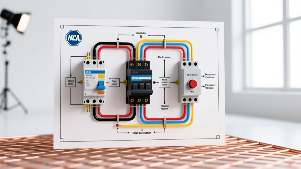
A standard ISO 5-pin relay uses four pins for a basic high-amperage switch. Understanding the internal architecture is vital for proper diode placement and ECU protection.
- Pin 30 (Common / Power In): Connects to the battery positive via the main MEGA/AMI fuse. Use 10 AWG TXL wire.
- Pin 87 (Normally Open / Power Out): Connects directly to the positive terminal of the radiator fan motor. Use 10 AWG TXL wire.
- Pin 86 (Coil Power): Connects to a 12V ignition-switched source or the ECU fan-trigger output. Use 16 AWG TXL wire.
- Pin 85 (Coil Ground): Connects to the chassis ground or the thermal switch/ECU ground trigger. Use 16 AWG TXL wire.
- Pin 87a (Normally Closed): Left unconnected and insulated in this specific application.
Critical Safety Addition - The Flyback Diode: When the relay coil de-energizes, the collapsing magnetic field generates a high-voltage reverse spike (inductive kickback) that can instantly destroy an ECU driver transistor or weld a delicate thermal switch. You must solder a 1N5408 (3A, 1000V) flyback diode across pins 85 and 86, with the diode's cathode (silver stripe) pointing toward Pin 86 (12V+). This safely recirculates the spike back into the coil.
Wire Gauge, Fuse Sizing, and Voltage Drop Matrix
Sizing your wire based solely on 'ampacity' charts found on generic forums is dangerous. Automotive wiring must account for voltage drop over distance. A 12V fan operating at 10.5V due to undersized wire will draw more amperage to produce the same wattage, generating excess heat. The following matrix assumes a maximum 3% voltage drop (0.36V) at a 20-foot round-trip circuit length, adhering to NFPA 70 (NEC) guidelines for DC low-voltage safety.
| Fan Steady Draw | Inrush Spike | Recommended Wire (TXL) | Main Feed Fuse (Battery) | Branch Fuse (Post-Relay) |
|---|---|---|---|---|
| 10A - 15A | ~25A | 12 AWG | 30A AMI | 20A ATC |
| 16A - 25A | ~40A | 10 AWG | 40A MEGA | 30A ATC |
| 26A - 40A (Dual Fans) | ~65A | 8 AWG | 60A MEGA | 50A MAXI |
Step-by-Step Installation & Terminations
The physical execution of the radiator fan electric fan relay wiring diagram dictates its lifespan. Vibration and thermal cycling will destroy poor connections.
Step 1: Power Feed and Main Fusing
Disconnect the battery negative terminal. Route your main 10 AWG TXL wire from the battery positive post. Install a Littelfuse MEGA fuse holder within 7 inches of the terminal. This ensures that if the wire chafes against the chassis anywhere along its route, the fuse blows before a fire starts.
Step 2: Crimping vs. Soldering
Do not use twist-on wire nuts or electrical tape. For the high-amperage pins (30 and 87), use closed-barrel, nylon-insulated ring terminals crimped with a heavy-duty ratcheting crimper (e.g., Titan 11230). For the coil trigger wires (85 and 86), open-barrel crimps or high-quality solder joints sealed with adhesive-lined heat shrink are acceptable.
Step 3: Environmental Sealing
Wrap all terminations in 3M EPS300 Adhesive-Lined Heat Shrink. When heated, the inner thermoplastic adhesive melts and flows into the wire strands, creating a waterproof, corrosion-proof seal that blocks capillary action from wicking moisture into the copper strands.
Step 4: Loom and Routing
Encase the entire harness in split-loom tubing or, preferably, Tesa 51036 PET fleece tape. Fleece tape prevents the harness from rattling against the radiator support and withstands 150°C continuous heat, unlike cheap vinyl electrical tape which turns into a sticky, unraveling mess after one summer.
Troubleshooting Matrix: Edge Cases and Failure Modes
Even with a perfect diagram, real-world variables can cause system anomalies. Use this matrix to diagnose issues without blindly swapping parts.
| Symptom | Probable Root Cause | Diagnostic Action & Fix |
|---|---|---|
| Fan runs, but relay clicks rapidly or gets extremely hot. | Severe voltage drop on Pin 30 or Pin 87 causing coil starvation. | Measure voltage at Pin 30 with fan running. If below 11.5V, upgrade to 8 AWG wire or clean battery grounds. |
| Fan continues to run after ignition is off / thermal switch cools. | Relay contacts welded shut due to inrush arcing or missing flyback diode. | Tap relay with screwdriver handle. If fan stops, contacts are pitted. Replace with Bosch JD1912 and install 1N5408 diode. |
| ECU throws a 'Fan Circuit Open' code, fan doesn't trigger. | ECU PWM driver detects incorrect resistance or diode installed backward. | Verify diode cathode (stripe) faces Pin 86. Check for broken 16 AWG trigger wire using a multimeter continuity test. |
| Main MEGA fuse blows instantly upon fan startup. | Fan motor seized, or undersized fuse used for high-inrush dual-fan setup. | Spin fan blades by hand. If stiff, replace motor bearings. If free, verify MEGA fuse rating matches matrix above. |
Final Safety Audits
Before reconnecting the battery and applying power, perform a continuity check from the fan positive terminal to chassis ground to ensure no accidental shorts were introduced during routing. Once powered, use an infrared thermometer to scan the relay casing and fuse holder after 10 minutes of continuous fan operation. Temperatures exceeding 60°C (140°F) on the plastic relay housing indicate excessive resistance at the crimp terminals, requiring immediate re-termination. By adhering strictly to SAE wire standards, proper overcurrent protection, and inductive spike suppression, your cooling system will operate safely and reliably for the life of the vehicle.