
Decoding the GM 3-Wire Alternator: Beyond Basic Installation
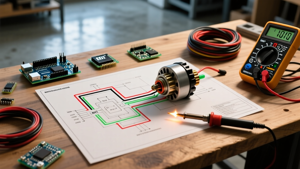
When restomodding a classic GM truck, maintaining an older muscle car, or building a custom rig in 2026, the Delco 10SI and 12SI 3-wire alternators remain the gold standard for reliable, self-contained charging. However, simply hooking up the wires based on a quick internet search often leads to chronic undercharging, overcharging, or dash-light anomalies. To truly diagnose these systems, you must use a wiring diagram for a GM 3 wire alternator not just as an installation map, but as a dynamic troubleshooting schematic.
Unlike modern LIN-bus controlled alternators found in 2026 late-model vehicles, the classic GM 3-wire unit relies on analog voltage sensing and physical excitation currents. By understanding the exact electrical path from the battery, through the ignition switch, and into the internal voltage regulator, you can isolate faults in minutes using a standard digital multimeter (DMM). According to the experts at MAD Electrical's Alternator Technical Guide, over 70% of 'failed' GM alternators returned to parts stores are actually perfectly functional units suffering from incorrect external wiring or voltage drop issues.
The Pinout: Mapping the Terminals
Looking at the rear of a standard Delco 10SI or 12SI alternator, you will see three distinct connection points. Understanding the internal regulator's relationship to these terminals is the key to accurate diagnostics.
- BAT Terminal (Main Output): The threaded stud that connects directly to the battery positive post (usually via the starter solenoid or a main distribution block). This carries the full amperage load of the alternator.
- Terminal #1 (L / Exciter / Lamp): The spade connector closest to the edge of the plastic housing. This terminal receives switched 12V from the ignition circuit, typically routed through the dash charge indicator bulb. It provides the initial 'excitation' current required to turn on the internal voltage regulator and start the charging process.
- Terminal #2 (S / Sense): The spade connector closest to the center of the housing. This is the voltage sense wire. It must be connected to a clean 12V source (ideally the battery positive terminal or main fuse block) so the internal regulator can read the actual system voltage and adjust the rotor field accordingly.
Expert Diagnostic Tip: Never jumper Terminal #1 and Terminal #2 together at the alternator plug. While this will make the alternator charge, it forces the regulator to sense voltage at the alternator case rather than the battery. Due to voltage drop across the main BAT wire, the battery will chronically undercharge by 0.5V to 1.2V, leading to premature sulfation and battery failure.
Multimeter Troubleshooting Matrix
Use the following matrix alongside your wiring diagram to pinpoint the exact location of a charging system fault. Ensure your DMM is set to DC Voltage and your battery is fully charged (12.6V resting) before beginning.
| Test Point (Refer to Diagram) | Engine Off (Key On) | Engine Running (No Load) | Engine Running (High Load) | Fault Indication if Out of Spec |
|---|---|---|---|---|
| BAT Stud | 12.4V - 12.6V | 13.8V - 14.4V | 13.5V - 14.2V | Bad main cable, faulty alternator diodes, or slipping belt. |
| Terminal #1 (L) | 11.5V - 12.2V | 13.8V - 14.4V | 13.5V - 14.2V | Open ignition circuit, burnt-out dash bulb, or broken wire. |
| Terminal #2 (S) | 12.4V - 12.6V | 13.8V - 14.4V | 13.5V - 14.2V | Broken sense wire, high resistance connection at battery. |
Step-by-Step Diagnostic Flow for No-Charge Conditions
When your vehicle's voltage drops below 12.5V while running, follow this systematic diagnostic flow derived from AA1Car's Charging System Diagnosis Library.
Step 1: Verify the Excitation Circuit (Terminal #1)
With the engine off and the key in the 'ON' position, probe Terminal #1. You should read battery voltage (minus a slight drop across the dash bulb, typically 11.5V+). If you read 0V, the alternator cannot excite. Check the dash charge light. If the bulb is burnt out, the circuit is open, and the alternator will not charge. Replace the bulb or wire a 50-ohm, 5-watt resistor in parallel with the bulb to ensure the circuit remains closed even if the filament fails.
Step 2: Verify the Sense Circuit (Terminal #2)
Probe Terminal #2 with the key on. It should read exact battery voltage. If Terminal #2 reads 0V, the internal regulator assumes the system is dead and will output zero voltage to prevent electrical fires. Trace the sense wire back to the battery or distribution block to find the break.
Step 3: Perform a Voltage Drop Test on the BAT Wire
As recommended in Fluke's Automotive Alternator Testing Guide, a voltage drop test is superior to simply checking for continuity. Set your DMM to DC Volts. Place the red probe on the alternator BAT stud and the black probe on the battery positive post. Run the engine and turn on headlights and the blower motor to create a load. A reading above 0.5V indicates excessive resistance in the main charging cable, requiring an upgrade to a heavier gauge wire or cleaning of the terminal lugs.
Edge Cases: Why Your 'Good' Alternator Isn't Charging
Even with a perfect wiring diagram for a GM 3 wire alternator, modern modifications can introduce unique failure modes that stump standard diagnostic procedures.
The LED Dash Light Trap
In 2026, most classic car restorations utilize LED dash clusters. LEDs draw virtually zero current compared to incandescent bulbs. Terminal #1 requires a minimum of 0.5 to 1.5 amps of initial current flow to 'wake up' the internal voltage regulator. If you wire Terminal #1 through an LED without a parallel load resistor, the alternator will not excite, and the battery will drain. Always install a 1N4001 diode and a 50-ohm resistor in the exciter wire when using LED dash indicators.
The Open Sense Wire Overcharge
If the wire connected to Terminal #2 breaks or loses continuity, the 10SI/12SI regulator defaults to sensing voltage internally at the alternator case. Because there is always voltage drop between the alternator and the battery, the regulator will artificially increase its output to try and reach 14.2V at the battery. This results at the alternator pushing 15.5V or higher, boiling the battery acid and frying sensitive modern electronics like EFI controllers and digital dashes.
Wire Gauge and Routing Specifications
Selecting the correct wire gauge is critical for safety and efficiency. The Delco 10SI was originally produced in 37A, 63A, and 94A variants, while the 12SI handles 94A and 108A. Using undersized wire creates a fire hazard and induces the voltage drop issues mentioned above.
- 37A - 63A Alternators: Use minimum 8 AWG copper wire for the main BAT feed if the run is under 36 inches. Use 6 AWG for longer runs or high-heat engine bays.
- 94A - 108A Alternators: Use minimum 6 AWG copper wire for runs under 24 inches. For runs exceeding 24 inches, or if routing near hot exhaust headers, step up to 4 AWG or 2 AWG high-strand count welding cable for maximum flexibility and conductivity.
- Terminal #1 and #2 Wires: 14 AWG or 12 AWG primary wire is perfectly sufficient, as these circuits carry less than 2 amps of current. Always use Tefzel (TXL) insulated wire in the engine bay to resist heat degradation and chemical exposure.
By treating the wiring diagram for a GM 3 wire alternator as a living diagnostic tool rather than a static installation guide, you eliminate guesswork. Whether you are chasing a parasitic draw, an overcharge condition, or a simple no-charge fault, systematic voltage testing at the BAT, #1, and #2 terminals will always reveal the true root cause of the electrical failure.