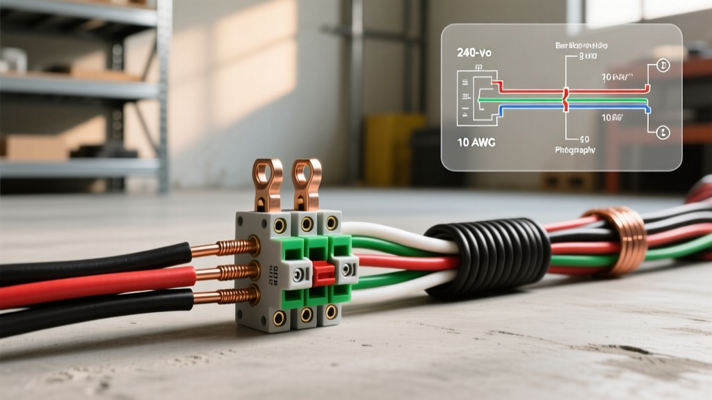

Decoding the 240 Volt Electric Heater Wiring Diagram
As energy grids modernize and residential electrification accelerates through 2026, electric resistance heating remains a staple for supplemental and zone heating. Whether you are installing a Cadet Com-Pak Plus CSP1522TW wall heater or a Stelpro baseboard unit, understanding the core 240 volt electric heater wiring diagram is critical for safety and code compliance. Unlike standard 120V receptacle circuits, a 240V heating circuit operates on a dedicated double-pole breaker, utilizing two ungrounded (hot) conductors and an equipment grounding conductor, typically omitting a neutral wire.
This comprehensive reference guide breaks down the exact wire gauge requirements, National Electrical Code (NEC) color code mandates, and the specific termination practices required to prevent thermal failure at the connection points.
Wire Gauge Selection: The 125% Continuous Load Rule
The most common mistake DIYers make when wiring 240V heaters is sizing the breaker and wire based purely on the heater's maximum amperage. According to NFPA 70 (National Electrical Code) Article 210.20(A) and Article 424.3(B), fixed electric heating equipment is classified as a continuous load because it is expected to operate for three hours or more. Therefore, the branch circuit must be sized at 125% of the heater's rated current.
Sizing Matrix: Wattage to Wire Gauge
The table below provides the exact mathematical breakdown for standard residential 240V heaters. While 14 AWG is technically permissible for loads under 16A on a 15A breaker, professional electricians in 2026 universally default to 12 AWG to mitigate voltage drop over long runs and accommodate future smart-thermostat upgrades.
| Heater Wattage (240V) | Base Amperage | 125% Continuous Load | Minimum Wire Gauge (NM-B) | Required Breaker Size |
|---|---|---|---|---|
| 1000W | 4.16A | 5.20A | 14 AWG (12 AWG preferred) | 15A Double-Pole |
| 1500W | 6.25A | 7.81A | 14 AWG (12 AWG preferred) | 15A Double-Pole |
| 2000W | 8.33A | 10.41A | 12 AWG | 15A or 20A Double-Pole |
| 2500W | 10.41A | 13.01A | 12 AWG | 20A Double-Pole |
| 3000W | 12.50A | 15.62A | 12 AWG | 20A Double-Pole |
| 4000W | 16.66A | 20.82A | 10 AWG | 30A Double-Pole |
NEC Color Code Requirements for 240V Heating Circuits
Color coding in 240V circuits is strictly governed by NEC Article 200.7 and 210.4. Because standard 2-wire NM-B (Romex) cable contains a black, white, and bare copper wire, you must properly re-identify the white wire when used as a hot conductor.
Scenario A: Standard Line-Voltage Thermostat (No Neutral Required)
When wiring a basic mechanical or digital line-voltage thermostat (like the Honeywell CT410B) to a standard baseboard heater, you will typically use 12/2 NM-B cable.
- Black Wire: Ungrounded conductor (Hot 1). Connects to one pole of the double-pole breaker and the 'Line 1' terminal on the thermostat.
- White Wire: Ungrounded conductor (Hot 2). Must be re-identified with black or red electrical tape (or heat shrink) at both the panel and the thermostat box. Connects to the second pole of the breaker and 'Line 2'.
- Bare Copper: Equipment grounding conductor. Connects to the ground bus bar, the metal junction box, and the heater chassis ground screw.
NEC Code Warning: Failing to re-identify the white wire with colored tape or permanent marker at every point where the cable is accessible violates NEC 200.7(C)(2). Inspectors will immediately flag this during a rough-in or final electrical inspection.
Scenario B: Smart Thermostats & Fan-Forced Heaters (Neutral Required)
The 2026 market is dominated by Wi-Fi-enabled smart thermostats (such as the Mysa Smart Thermostat or Stelpro Maestro). These devices require a 120V reference voltage to power their internal radios and displays. Furthermore, fan-forced heaters often use 120V blower motors while running the heating elements at 240V.
In these cases, you must run 12/3 or 10/3 NM-B cable from the panel:
- Black Wire: Hot 1 (Line 1)
- Red Wire: Hot 2 (Line 2)
- White Wire: Grounded Neutral (Connects to the neutral bus bar in the panel; do not tape this wire).
- Bare Copper: Ground.
Step-by-Step: Wiring the Double-Pole Breaker
Proper termination at the main service panel is where many electrical fires originate due to loose connections and thermal creep. Follow this sequence for a Square D Homeline or Siemens QP double-pole breaker:
- Kill Main Power: Verify zero voltage at the bus bars using a CAT III or CAT IV non-contact voltage tester and a digital multimeter.
- Strip the Sheathing: Remove exactly 3/4 inch of insulation from the black and re-identified white (or red) conductors using a precision wire stripper. Do not nick the copper.
- Terminate Hots: Insert the black wire into one terminal of the double-pole breaker and the red/taped-white into the other. Torque the terminal screws to the manufacturer's specification (typically 20-25 in-lbs for standard residential breakers).
- Land the Ground: Connect the bare copper wire to the equipment grounding bus bar. Never land a ground wire on the neutral bus bar in a main panel, and absolutely never on the neutral bar in a sub-panel.
- Snap and Test: Snap the breaker into the hot bus bars, restore main power, and test for 240V across the two hot terminals before connecting the downstream thermostat.
Common Failure Modes & Troubleshooting
According to data referenced by the U.S. Department of Energy, electric resistance heaters are nearly 100% efficient at the point of use, meaning almost all wiring losses manifest as heat. If your installation fails prematurely, investigate these specific edge cases:
1. Thermal Creep on Wire Nuts
Standard yellow or red plastic wire nuts are not rated for the ambient heat generated inside a baseboard heater junction box, which can easily exceed 140°F (60°C). Over time, the copper expands and contracts, loosening the connection. Solution: Always use high-temperature ceramic wire connectors or copper crimp sleeves rated for at least 150°C (300°F) inside the heater's built-in junction box.
2. Voltage Drop on Long Runs
If you are wiring a garage or detached workshop heater located more than 80 feet from the main panel, 12 AWG wire will suffer from significant voltage drop, causing the heater to underperform and the blower motor to overheat. Solution: Upsize to 10 AWG copper or 8 AWG aluminum for runs exceeding 75 feet on a 20A circuit.
3. Backfed Neutral on Smart Thermostats
Some DIYers attempt to power a smart thermostat by 'borrowing' a neutral from an adjacent 120V lighting circuit. This creates a multi-wire branch circuit (MWBC) violation if not handled with a common-trip breaker, and can cause backfeed currents that destroy the thermostat's internal relay. Always pull a dedicated 3-wire cable from the same double-pole breaker.
Frequently Asked Questions
Can I use a single-pole 240V breaker?
No. In North America, residential 240V is achieved by spanning two 120V legs that are 180 degrees out of phase. You must use a double-pole breaker with a common internal trip mechanism (or an approved handle tie) to ensure both hot legs disconnect simultaneously during a fault, as mandated by NEC 240.15.
Does a 240V baseboard heater need a disconnect switch?
NEC Article 424.19 requires a disconnecting means that is 'within sight' of the heater. A line-voltage thermostat with a positive 'OFF' position satisfies this requirement. If your thermostat only has a 'Low' setting or is a smart relay without a physical hard-off switch, you must install a separate 2-pole toggle disconnect switch or ensure the breaker is lockable.
What is the 2026 average cost for materials?
As of early 2026, a 250-foot roll of 12/2 NM-B copper wire averages $115-$130. A standard 20A double-pole breaker costs between $10 and $15, while a high-quality digital line-voltage thermostat ranges from $45 to $85. Always factor in the cost of high-temp ceramic wire nuts and cable staples for a fully code-compliant installation.