
Decoding the Wiring Diagram for a Doorbell: Line vs. Low Voltage
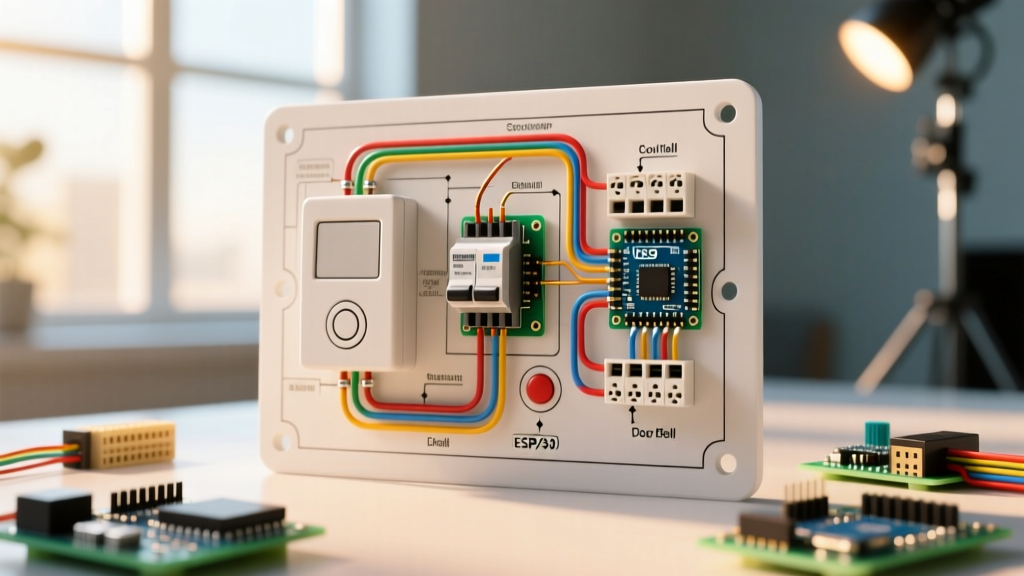
When most DIYers search for a wiring diagram for a doorbell, they are immediately presented with low-voltage schematics showing a button, a chime, and a transformer. However, as a Panel & Breaker Guide, we must address the true origin of the circuit: the main electrical panel. A doorbell is fundamentally a two-stage system. Stage one is the 120V line-voltage circuit originating at your breaker box. Stage two is the stepped-down Class 2 low-voltage circuit (typically 16VAC to 24VAC) that powers the button and chime.
In 2026, the proliferation of smart video doorbells (like the Ring Pro 2 and Nest Doorbell Wired) has drastically changed the power requirements for this seemingly simple circuit. Older homes were wired with 10VA (Volt-Ampere) transformers, which are entirely insufficient for modern smart hubs that demand continuous 30VA to 40VA. This guide breaks down the exact breaker sizing, wire gauge selection, and panel-side termination procedures required to safely wire a doorbell circuit from the main service panel to the transformer junction box.
Component Selection & Breaker Sizing Matrix
Doorbell transformers are governed by NFPA 70 (National Electrical Code), specifically Article 411 and Article 725 for Class 2 circuits. The line-voltage side feeding the transformer must be protected by a standard branch circuit breaker. While a doorbell transformer draws minimal current (a 40VA transformer at 120V draws only 0.33 Amps), the breaker's primary job is to protect the wire, not the transformer.
| Breaker Size | Wire Gauge (NM-B) | Max Transformer VA | Typical Use Case | Est. Material Cost (2026) |
|---|---|---|---|---|
| 15A Single-Pole | 14 AWG | 40VA | Dedicated doorbell circuit, standard chimes | $6.50 (Breaker) + $0.45/ft (Wire) |
| 20A Single-Pole | 12 AWG | 40VA | Shared with lighting or general receptacles | $7.25 (Breaker) + $0.65/ft (Wire) |
Note: Never install a breaker larger than 20A for a Class 2 transformer supply circuit. NEC Article 725.121 explicitly restricts the branch circuit supplying a Class 2 transformer to a maximum of 20 amperes.
Step-by-Step: Panel to Transformer Wiring Procedure
Executing the line-voltage portion of the wiring diagram for a doorbell requires strict adherence to panel safety and termination torque specifications. Below is the professional workflow for installing a new dedicated 15A doorbell circuit.
1. Panel Preparation and Breaker Installation
Turn off the main breaker to de-energize the panel bus bars. Select an available single-slot space. For a standard Square D Homeline panel, install a HOM115 (15A Single-Pole Breaker). Snap the breaker onto the hot bus bar stab. Route your 14/2 NM-B (Romex) cable through a knockout using a 3/8-inch NM cable connector, ensuring the internal clamp secures the jacket without pinching the inner conductors.
2. Line-Voltage Terminations
Strip the 14/2 NM-B jacket back to within 1/4 inch of the cable clamp. Strip exactly 1/2 inch of insulation from the black (hot) and white (neutral) conductors.
- Ground: Terminate the bare copper ground wire to the panel's ground bus bar. Torque to 20 in-lbs.
- Neutral: Terminate the white wire to the neutral bus bar (or combined neutral/ground bar in main service panels). Torque to 20 in-lbs.
- Hot: Terminate the black wire to the HOM115 breaker lug. Torque to 20 in-lbs. Proper torque prevents loose connections that cause arcing and thermal failures at the breaker.
3. Transformer Junction Box Mounting
The transformer must not be left hanging by its wire pigtails. Mount a standard 1-gang or 4x4 junction box (e.g., Carlon B114B nail-on box) near an existing power source if sharing a circuit, or at the end of your dedicated 14/2 run. The transformer plugs into a standard 120V receptacle inside the box, or hardwires directly using wire nuts. For hardwired models like the Honeywell AT72P16, use WAGO 221 lever-nuts to connect the 14/2 line voltage to the transformer's 120V pigtails.
Transformer Selection: Standard vs. Smart Doorbells
The most common point of failure in modern doorbell wiring is an undersized transformer. If you are upgrading to a smart doorbell, your wiring diagram must account for continuous Wi-Fi streaming and night-vision power draws.
- Legacy Mechanical Chimes (16VAC, 10VA): Found in homes built before 1995. Sufficient only for simple solenoid chimes and basic push-buttons. Will cause a smart doorbell to reboot continuously or fail to charge.
- Standard Smart Upgrades (16VAC, 20VA): The minimum acceptable baseline for basic video doorbells (e.g., standard Ring Video Doorbell Wired). Priced around $18 in 2026.
- High-Demand Smart Hubs (24VAC, 30VA to 40VA): Required for advanced models like the Ring Pro 2, Nest Doorbell (Wired), and systems integrating with smart home hubs. The Ring Hardwired Transformer (24VAC, 40VA) retails for approximately $32 and provides the necessary overhead to prevent voltage sag during night-vision activation.
Low-Voltage Routing and NEC Compliance
Once the transformer is energized, the low-voltage side begins. Use 18/2 CPE (Chime and Thermostat Wire) for standard runs under 50 feet. For runs exceeding 50 feet, upgrade to 16/2 wire to mitigate voltage drop, which can cause smart doorbells to register as 'offline' in their companion apps.
According to OSHA and NEC electrical safety guidelines, Class 2 low-voltage wires must not share the same conduit, junction box, or staple hole with 120V line-voltage wires. Maintain a minimum separation of 2 inches between the 18/2 doorbell wire and any 14/2 or 12/2 NM-B cables to prevent electromagnetic interference (EMI) and induced phantom voltages, which can cause mechanical chimes to hum or buzz continuously.
Edge Cases & Failure Modes at the Breaker Panel
When troubleshooting a dead doorbell, electricians rarely look at the panel first, but panel-side anomalies do occur. Here are specific failure modes to check:
Diagnostic Callout: The 'Tripped but Not Flipped' Breaker
If your doorbell transformer is dead, check the breaker handle. A tripped Square D breaker often stops in the middle 'neutral' position rather than flipping fully to 'OFF'. Push the handle firmly to 'OFF' until you hear a click, then reset to 'ON'. If it immediately trips again, you have a dead short in the 14/2 NM-B line or a failed transformer primary coil.
- Shared Neutral Overload: If the doorbell transformer was wired as part of a Multi-Wire Branch Circuit (MWBC) and the neutral is disconnected at the panel, the transformer may receive 240V instead of 120V, instantly vaporizing the primary coil and destroying the unit.
- Backstabbed Receptacles: If the transformer plugs into a receptacle rather than hardwiring, ensure the receptacle is not wired using push-in 'backstab' terminals. These terminals frequently lose grip over time due to thermal cycling, cutting power to the doorbell intermittently.
- Transformer Hum at the Panel: A loud buzzing originating from the breaker panel when the doorbell button is pressed indicates a loose bus bar connection or a failing breaker lug, not a doorbell issue. This requires immediate thermal imaging and retorquing by a licensed electrician.
Frequently Asked Questions
Can I wire a doorbell transformer to a 20A kitchen circuit?
Technically, NEC Article 725 allows a Class 2 transformer to be supplied by a 20A circuit. However, local AHJs (Authorities Having Jurisdiction) often prohibit tapping into required small-appliance branch circuits (kitchens and dining rooms) for non-kitchen loads like doorbells. It is best practice to tap into a general lighting circuit or run a dedicated 15A line.
Why does my smart doorbell say 'Poor Voltage' even with a new 30VA transformer?
This is almost always a wire gauge or distance issue. If you are using 20/2 wire (often mistakenly sold as doorbell wire but actually intended for telecom), the resistance over a 40-foot run will drop your 24VAC down to 18VAC by the time it reaches the doorbell. Replace the run with 18/2 or 16/2 CPE wire to resolve the voltage drop.
Does the doorbell transformer need to be grounded?
The line-voltage junction box housing the transformer must be grounded via the 14/2 NM-B bare copper wire. However, the low-voltage 16VAC/24VAC secondary side of the transformer is isolated and does not require a ground wire for the button or chime circuit.