
Understanding the Franklin Electric 3-Wire Control Box
When installing or repairing a submersible well pump, interpreting a Franklin Electric control box wiring diagram is a foundational skill for both seasoned electricians and advanced DIYers. Unlike 2-wire pumps that house their starting components underground, 3-wire systems rely on an above-ground control box to manage the start and run capacitors, as well as the potential relay. This setup dramatically extends the lifespan of the motor by keeping heat-sensitive components out of the well bore.
In 2026, the Franklin Electric QD (Quick Disconnect) Standard and Deluxe control boxes remain the industry standard for residential 230V applications, typically ranging from $145 to $285 depending on the horsepower (HP) rating. Whether you are wiring a 1/2 HP model (like the 50715051) or a 3 HP heavy-duty unit, the fundamental wiring architecture remains consistent. This tutorial will walk you through the exact terminal connections, component functions, and National Electrical Code (NEC) compliance requirements for a safe, long-lasting installation.
Core Components Inside the Control Box
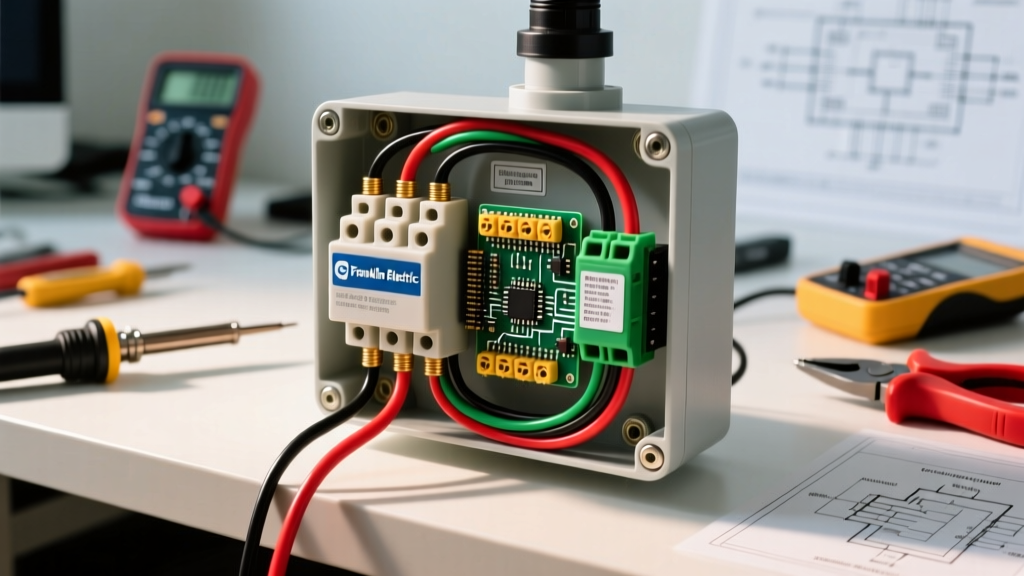
Before making any connections, it is vital to understand what you are wiring. A standard Franklin Electric 3-wire control box contains three primary electromechanical components:
- Start Capacitor: Provides the high-torque phase shift needed to overcome the initial inertia of the submerged pump motor. It is only in the circuit for a fraction of a second.
- Run Capacitor: Remains in the circuit during continuous operation to improve motor efficiency and power factor, reducing overall amperage draw and heat generation.
- Potential Relay: Monitors the back-EMF (electromotive force) of the motor. Once the motor reaches approximately 75% of its rated RPM, the relay opens, disconnecting the start capacitor to prevent it from exploding.
Step-by-Step Franklin Electric Control Box Wiring Diagram
The physical wiring of a Franklin Electric box is divided into two distinct zones: the Line Side (power from the breaker panel) and the Load Side (power down the well to the pump). Below is the precise wiring sequence for a standard 230V single-phase 3-wire system.
1. Line Side Connections (Power In)
Feed your 230V duplex breaker circuit into the top conduit hub of the control box. You will be working with three wires: two hot legs and one equipment grounding conductor.
- Hot Leg 1 (Black or Red wire): Connect to the L1 terminal on the top terminal block.
- Hot Leg 2 (Black or Red wire): Connect to the L2 terminal on the top terminal block. (Note: 230V single-phase is non-polarized; L1 and L2 are interchangeable).
- Ground (Bare copper or Green wire): Terminate this directly to the Ground Bus Bar or the designated green grounding screw inside the metal enclosure. Do not connect the ground to L1 or L2.
2. Load Side Connections (Pump Drop Cable)
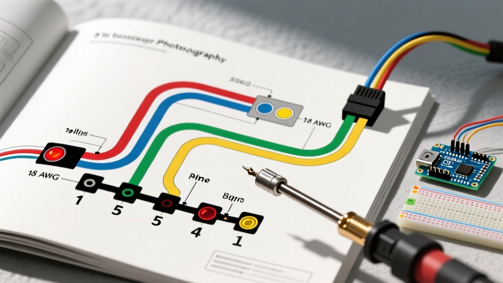
Franklin Electric 3-wire submersible drop cables are universally color-coded. The bottom terminal block on the control box is labeled specifically for these colors. Strip exactly 3/8-inch of insulation from the drop cable wires to ensure full contact without exposing bare copper outside the terminal.
- Red Wire (Common): Connect to the R terminal.
- Yellow Wire (Start): Connect to the Y terminal.
- Black Wire (Run): Connect to the B terminal.
- Green Wire (Ground): Connect to the Ground Bus Bar, joining the line-side ground.
3. Terminal Torque Specifications
A leading cause of control box failure in the first year of operation is loose terminal connections, which cause arcing and melt the bakelite terminal blocks. Use a calibrated torque screwdriver to tighten all line and load terminal screws to 12 to 15 inch-pounds, as specified in the 2026 Franklin Electric AIM (Application, Installation, and Maintenance) manual.
Wire Gauge Selection for Submersible Pumps
Using the correct wire gauge for the drop cable is non-negotiable. Voltage drop over long distances can cause the potential relay to fail to engage, keeping the start capacitor in the circuit until it vents or explodes. Consult the table below, based on NEC Article 310 and Franklin Electric engineering guidelines, for 230V systems.
| Motor HP | Full Load Amps (FLA) | Up to 200 ft | 200 ft - 400 ft | 400 ft - 600 ft |
|---|---|---|---|---|
| 1/2 HP | 5.0 A | 14 AWG | 12 AWG | 10 AWG |
| 3/4 HP | 6.9 A | 12 AWG | 10 AWG | 8 AWG |
| 1.0 HP | 8.7 A | 12 AWG | 10 AWG | 8 AWG |
| 1.5 HP | 10.6 A | 10 AWG | 8 AWG | 6 AWG |
| 2.0 HP | 13.2 A | 10 AWG | 8 AWG | 6 AWG |
| 3.0 HP | 17.0 A | 8 AWG | 6 AWG | 4 AWG |
Note: Always size your duplex breaker according to the motor's Service Factor Amps (SFA), not just the FLA. For a 1.5 HP motor with an SFA of 12.5A, a 15A or 20A breaker is typically required.
Troubleshooting Common Wiring & Component Failures
Even with a perfect wiring diagram execution, environmental factors and component aging can cause faults. Use a digital multimeter (like the Fluke 87V) set to the appropriate Ohms or Microfarad (µF) settings to diagnose these common issues.
| Symptom | Probable Cause | Multimeter Test & Solution |
|---|---|---|
| Motor hums loudly but fails to start; breaker trips after 5 seconds. | Failed Start Capacitor or stuck Potential Relay. | Test start capacitor for µF rating. If reading is >10% below the printed rating, replace. Check relay coil for continuity; replace if open. |
| Pump starts, runs for 2 seconds, then trips the breaker. | Start capacitor not disconnecting (Relay failure). | The potential relay contacts are likely welded shut. Replace the relay immediately to prevent motor burnout. |
| Zero voltage at the Load Side (R, Y, B) when breaker is on. | Tripped internal overload or broken line-side connection. | Check L1 and L2 for 230V. If present, locate the red reset button on the internal overload protector and press. If it won't reset, the overload is dead. |
| Pump runs continuously but delivers low water pressure. | Worn pump impellers or drop cable voltage drop. | Measure voltage at the load terminals while running. If it drops below 210V, upgrade the drop cable wire gauge. |
Grounding and NEC Code Compliance
Water and electricity are a lethal combination. The National Electrical Code (NEC) mandates strict grounding protocols for submersible well systems. According to NEC Article 250.112, the metal control box enclosure, the well casing, and the motor housing must all be bonded to a continuous equipment grounding conductor.
'Fixed equipment that is connected to the earth shall be grounded and bonded in accordance with the requirements of Article 250.' — NEC 2023/2026 Edition
Never rely on the well casing alone as a ground path. Corrosion at the pitless adapter can break this path, leaving the water supply energized in the event of an internal motor short. Always run a dedicated, insulated copper ground wire (Green) inside the conduit alongside your hot legs, and bond it to both the control box ground bus and a grounding clamp on the steel well casing.
Maintaining Your 3-Wire System
For comprehensive maintenance schedules and advanced diagnostic procedures, professionals frequently reference resources like the Penn State Extension Water Systems Maintenance guides, which provide excellent regional data on how hard water and mineral buildup affect above-ground control components. Additionally, verifying your specific terminal layout against the official Franklin Electric Control Box product documentation ensures you account for any mid-year manufacturing revisions to the QD or SubDrive series.
Frequently Asked Questions
Can I convert a 3-wire Franklin pump to a 2-wire system?
No. A 3-wire motor requires the external phase shift provided by the control box. If you wish to eliminate the control box, you must pull the pump and replace it with a dedicated 2-wire submersible motor that contains an internal starting switch.
Why is my Franklin control box buzzing?
A loud 60Hz buzz usually indicates a failing potential relay or a start capacitor that is bulging and failing internally. It can also occur if the line voltage is severely unbalanced or dropping below 200V due to undersized feeder wires from the main panel.
Does the control box need to be mounted vertically?
Yes. Franklin Electric specifies that standard QD control boxes must be mounted vertically with the conduit hubs facing up and down. Mounting the box sideways or upside down alters the gravity-dependent operation of the internal potential relay and can cause the start capacitor to remain in the circuit too long, leading to catastrophic failure.