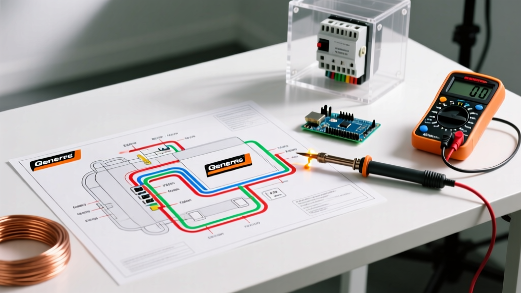

The Critical Intersection of Generac Wiring Diagrams and NEC Safety Codes
As grid instability continues to drive residential and commercial backup power adoption in 2026, the wiring diagram for Generac generator installations has become one of the most frequently referenced documents in the electrical trades. However, simply connecting wires to make the unit run is a dangerous oversimplification. For electrical professionals and advanced DIYers, interpreting these diagrams through the lens of the National Electrical Code (NEC) is mandatory to prevent backfeeding, fire hazards, and catastrophic equipment failure.
Whether you are installing a flagship Generac Guardian Series 24kW (Model 7044) or a commercial Protac 45kW liquid-cooled unit, the control and power wiring must strictly adhere to NEC Article 702 (Optional Standby Systems) and local utility interconnection agreements. This guide dissects the core wiring schematics, translating Generac's terminal designations into actionable, code-compliant installation protocols.
Decoding the Core Wiring Diagram for Generac Generator Terminals
The main junction box inside a Generac air-cooled generator features two distinct wiring domains: high-voltage AC power routing and low-voltage DC control signaling. Misinterpreting these on the wiring diagram is the leading cause of controller board burnout and utility lineworker endangerment.
1. High-Voltage AC Power Lugs (E1, E2, N, G)
The primary power output from the generator's alternator routes through the main circuit breaker before terminating at the utility transfer switch. According to the Generac Official Product Manuals, the standard terminal designations are:
- E1 & E2 (Hot Legs): These carry the 240VAC split-phase output. For a 200-amp service using the Generac RTX200A3 transfer switch, you must use 2/0 AWG THHN/THWN-2 copper conductors. If the run exceeds 50 feet, upsizing to 3/0 AWG is required to maintain voltage drop below 3%.
- N (Neutral): The current-carrying neutral conductor. Code Alert: Under NEC 250.142, the neutral must be switched and isolated if the transfer switch is configured as a Separately Derived System.
- G (Equipment Ground): Bonds the generator chassis to the grounding electrode system. This must be a minimum of 6 AWG bare copper, tied to a dedicated ground rod (minimum 8-foot copper-clad) driven at the generator pad, per NEC 250.53.
2. The 7-Wire Low-Voltage Control Harness
The control harness is the nervous system of the automatic transfer sequence. The wiring diagram for Generac generator models typically routes these through a dedicated conduit to the transfer switch's control module.
- N1 & N2 (Utility Sense): These 120VAC lines monitor utility grid health. They must be connected to the utility side of the main service disconnect. Edge Case: If N1/N2 are wired to the load side of the transfer switch, the generator will never detect a utility outage, resulting in a total failure to start.
- T1 (Start Signal): A 12VDC signal that initiates the engine crank sequence. While 18 AWG is shown on basic diagrams, professional installers use 14 AWG for runs over 40 feet to prevent voltage drop below the 9VDC threshold required by the Evolution 2.0 controller.
- 192 (Battery Charger Power): Provides 120VAC to the internal battery charger. Must be on a dedicated 15A breaker.
- 0 (Common Ground): The DC return path for the control circuit. Must never be bonded to the AC neutral inside the generator.
NEC Code Compliance Matrix for Standby Generators
Adhering to the wiring diagram is only half the battle. The physical installation and system architecture must satisfy the latest NEC standards. Below is a compliance matrix referencing the 2023/2026 NEC cycle and NFPA 70: National Electrical Code guidelines.
| NEC Article / Standard | Requirement Description | Generac Installation Application |
|---|---|---|
| NEC 702.5 (Transfer Equipment) | Transfer equipment must prevent inadvertent interconnection of sources. | Use mechanically interlocked Generac RTX or RXSC switches. Never use manual breaker interlock kits for automatic standby setups. |
| NEC 702.7 (Signals) | Audible/visual signals required to indicate utility failure and generator status. | Generac's Wi-Fi enabled Mobile Link module satisfies this, provided the homeowner configures push alerts for fault codes. |
| NEC 250.30 (Grounding) | Grounding of AC supply systems (Separately Derived vs. Non-SDS). | If using a non-SDS transfer switch (RTX), do NOT bond neutral to ground at the generator. If using SDS (RXSC with switched neutral), bond N to G at the generator. |
| NFPA 37 (Clearances) | Minimum 18 inches from combustible walls; 5 feet from window/door openings. | Measure 5 feet from the exhaust side of the Generac enclosure to any structural air intake or operable window to prevent carbon monoxide ingress. |
Transfer Switch Architecture: RTX vs. RXSC Service Entrance
The wiring diagram changes significantly depending on whether you select a Generac RTX (Non-Service Rated) or RXSC (Service Entrance Rated) transfer switch. This decision dictates how the main utility feed is managed.
The Non-Service Rated Route (RTX Series)
The RTX switch must be installed downstream of the main utility service disconnect. In this configuration, the utility meter feeds a main breaker panel, which then feeds the RTX switch via a sub-feed breaker. The generator neutral is routed straight through, and the neutral-ground bond remains exclusively at the main utility panel. This is the most common retrofit scenario, with hardware costs for a 200A RTX switch averaging $850 in 2026.
The Service Entrance Route (RXSC Series)
The RXSC switch acts as the main service disconnect for the entire property. Utility power feeds directly from the meter into the RXSC. Because the RXSC switches the neutral (creating a Separately Derived System when on generator power), the neutral-to-ground bond must be established inside the generator enclosure. This setup requires pulling a 4-wire feeder (E1, E2, N, G) plus the control harness, and costs approximately $1,150 for the switch. As highlighted by OSHA Generator Safety Guidelines, proper neutral switching in SDS configurations is vital to prevent stray neutral currents from energizing equipment grounding conductors during utility outages.
Real-World Failure Modes and Edge Cases
Even when following the wiring diagram for Generac generator setups to the letter, environmental and edge-case variables can cause system faults. Expert troubleshooters look for these specific anomalies:
- Utility Sense Voltage Drop (N1/N2): If the utility sense wires are run over 150 feet using 18 AWG wire, voltage drop can cause the Generac controller to read the utility as 195V instead of 220V. The Evolution controller will interpret this as a brownout and initiate nuisance start-ups. Fix: Always use 12 AWG THHN for N1/N2 runs exceeding 75 feet.
- Floating Neutral Faults: If an installer forgets to remove the factory neutral-ground bonding strap inside a Generac unit when wiring it to a Non-SDS (RTX) switch, parallel neutral paths are created. This causes GFCI breakers in the home to trip randomly and can overheat the equipment ground wire. Always verify the bonding strap status against the transfer switch type.
- T1 Wire Induced Voltage: Running the low-voltage T1/192/0 control harness in the same conduit as the 240VAC E1/E2 power lines induces electromagnetic interference (EMI). This can cause the controller to receive phantom start signals. NEC 725.136 requires physical separation or the use of a metallic barrier between Class 1 (power) and Class 2 (control) circuits.
Expert Insight: Never rely solely on the pre-wired pigtails inside the transfer switch enclosure. Always verify the torque specifications on the E1, E2, and Neutral lugs using a calibrated inch-pound torque screwdriver. Generac specifies 250 in-lbs for 2/0 AWG terminals; under-torqued lugs will arc and melt under the sustained 100-amp continuous loads typical of modern all-electric homes during an outage.
Final Safety Verification Protocol
Before initiating the first automatic transfer test, execute a rigorous safety audit. Verify that the utility main breaker is isolated from the generator bus via the mechanical interlock. Test the N1 and N2 lines with a multimeter to confirm 120VAC to ground on each leg. Finally, ensure the grounding electrode conductor is securely clamped to both the generator chassis and the local ground rod. By treating the wiring diagram not just as a map, but as a strict code-compliance checklist, you ensure a resilient, safe, and legally sound backup power system capable of handling the electrical demands of 2026 and beyond.