
The Anatomy of a Dual Car Stereo Wiring Diagram
Installing a dual car stereo system—typically configured as a front cabin head unit paired with a rear entertainment zone, or a main dash unit alongside a dedicated marine/RV zone—requires more than just splicing into an existing 12V accessory wire. When you search for a wiring diagram for a dual car stereo, most consumer guides focus on RCA routing and speaker phase. However, from a Panel & Breaker perspective, the critical challenge lies in power distribution, inrush current management, and circuit protection.
Running two modern head units (such as a Pioneer DMH-W2770NEX and an Alpine iLX-W65T) on a single factory 10A or 15A fuse tap is a recipe for voltage drop, blown fuses, and potential thermal events. Modern digital amplifiers and capacitive touchscreens draw significant transient current upon startup. This guide details how to design a dedicated 12V DC distribution panel to safely power a dual-stereo configuration in 2026.
Why a Single-Circuit Splice Fails
Factory automotive wiring is engineered for the specific parasitic draw and inrush current of the OEM radio. Splicing a second stereo's constant 12V (yellow) and switched 12V (red) wires into the factory harness often exceeds the capacity of the OEM fuse. Furthermore, long wire runs to the rear cabin introduce resistance. According to standard automotive electrical principles outlined by Crutchfield's installation guidelines, voltage drop across undersized wires causes head units to reboot randomly when bass transients demand peak current.
Panel & Breaker Guide: Sizing Your Protection
To execute a professional wiring diagram for a dual car stereo, you must abandon inline glass fuses and adopt a centralized marine-style fuse block. This allows for individual branch circuit protection and a single, heavy-gauge main feed.
The Main Feed Breaker
The main power wire running from the vehicle's battery to your distribution panel must be protected within 7 inches of the battery terminal. For a dual stereo setup drawing a combined continuous 15A (with peaks up to 25A), a 40A ANL fuse or a marine-rated thermal circuit breaker is required. We recommend the Bussmann FWJ series or a Blue Sea Systems 40A ANL Fuse Block.
Branch Circuit Fusing Matrix
Each stereo requires its own dedicated branch on the fuse panel. Below is the sizing matrix based on standard 2026 head unit specifications.
| Circuit Branch | Wire Color (Standard) | Function | Recommended ATC Blade Fuse | Wire Gauge (Under 8ft) |
|---|---|---|---|---|
| Stereo 1 (Front) | Yellow | Constant 12V (Memory) | 5A | 16 AWG |
| Stereo 1 (Front) | Red | Switched 12V (Ignition) | 10A | 14 AWG |
| Stereo 2 (Rear) | Yellow | Constant 12V (Memory) | 5A | 14 AWG |
| Stereo 2 (Rear) | Red | Switched 12V (Ignition) | 10A | 12 AWG |
Note: The rear stereo requires a thicker wire gauge (12 AWG vs 14 AWG) for the switched line to compensate for the extended physical distance from the front-mounted fuse panel to the rear cabin or trunk.
Wire Gauge Selection & Voltage Drop Management
When planning your wiring diagram for a dual car stereo, you must calculate voltage drop. The automotive standard allows a maximum 3% voltage drop for sensitive electronics. At 12.6V, a 3% drop means your head unit should never see less than 12.22V under load.
Expert Warning on CCA Wire: As of 2026, the market is flooded with Copper-Clad Aluminum (CCA) wire marketed as OFC (Oxygen-Free Copper). CCA has up to 40% higher resistance than pure copper. Always verify your wire is certified OFC when sizing your main panel feed. If you must use CCA, step up one full AWG size to compensate for the resistance.
For the main feed from the battery to a centralized Blue Sea Systems ST Blade Fuse Block, use 8 AWG OFC wire if the run is under 10 feet, or 6 AWG OFC for runs exceeding 10 feet (common in extended cab trucks or RVs).
Step-by-Step: Routing Power Through a Fuse Panel
Follow this sequence to ensure your panel and breaker integration meets NFPA 70 (National Electrical Code) Article 551 standards for recreational vehicle 12V DC systems, which closely mirrors best practices for dual-zone automotive audio.
1. Install the Main Battery Breaker
Disconnect the negative battery terminal. Install a 40A ANL fuse holder on the positive terminal. Crimp a ring terminal onto your 8 AWG main power wire and secure it under the ANL fuse. Route the wire through the firewall using an existing rubber grommet—never pierce a new hole without a protective rubber firewall bushing to prevent chassis shorts.
2. Mount the Distribution Hub
Mount a 6-circuit or 12-circuit marine fuse block (e.g., Blue Sea Systems 5025) under the dash, away from the driver's pedals and HVAC moving parts. Connect the 8 AWG main feed to the fuse block's positive busbar. Connect a matching 8 AWG ground wire from the negative busbar to a verified, unpainted chassis ground point within 18 inches of the panel.
3. Wire the Individual Stereo Branches
Run individual 14 AWG and 12 AWG wires from the fuse block's protected circuits to the rear of Stereo 1 and Stereo 2. Use a relay for the switched 12V (red wire) if you are triggering both stereos from a single low-amperage OEM ignition source. A standard 30A Bosch-style 5-pin relay will handle the combined inrush current of both units' switched circuits without overloading the factory ignition switch.
Grounding Strategy: Avoiding Alternator Whine
The most common failure in dual car stereo wiring diagrams is ground loop-induced alternator whine. When two head units share a daisy-chained ground wire, the varying current draw of one unit modulates the ground reference of the other, creating an audible high-pitched whine that scales with engine RPM.
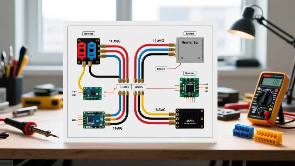
- Never Daisy-Chain Grounds: Run a dedicated 14 AWG ground wire from Stereo 1 and a separate 12 AWG ground wire from Stereo 2 directly to the chassis or to a centralized negative busbar.
- Sand the Chassis: Use 80-grit sandpaper to remove paint, clear coat, and rust at the grounding point. Secure with a stainless steel bolt and a star washer to bite into the bare metal.
- Apply Dielectric Grease: Coat the grounded terminal in dielectric grease to prevent oxidation, which increases resistance over time.
Troubleshooting Common Dual-Stereo Failures
Even with a perfect wiring diagram, real-world installations encounter edge cases. Here is how to troubleshoot them using a multimeter:
Issue: Rear Stereo Reboots During High Volume
Diagnosis: Voltage drop on the constant 12V line. The rear stereo is likely drawing peak current through 16 AWG wire over a 15-foot run, causing the voltage at the head unit to dip below 11V, triggering the unit's internal protection reboot.
Solution: Upgrade the constant and switched 12V feeds to 12 AWG OFC wire, and verify the branch fuse is not experiencing thermal fatigue.
Issue: Main ANL Fuse Blows Only When Both Units Power On
Diagnosis: Simultaneous inrush current. Capacitors inside both head units charge at the exact same millisecond, creating a momentary 45A+ spike that trips a 40A fast-acting breaker.
Solution: Install a 500-microfarad capacitor on the rear stereo's power feed to buffer the inrush, or use a staggered-turn-on relay with a 2-second delay timer module on the rear unit's remote turn-on lead.
Frequently Asked Questions
Can I use the factory antenna amplifier wire to trigger the second stereo?
No. The factory antenna amplifier wire typically provides only 100mA to 300mA. Using it to trigger a second stereo's relay coil and internal logic will overload the OEM circuit. Always use a dedicated relay triggered by the front stereo's "Amp Turn-On" (blue/white) wire.
Do I need a separate fuse block for the rear stereo?
Not necessarily, provided your main 8 AWG feed can handle the total amperage. However, if the rear stereo is located in a trailer or a large motorhome over 20 feet from the battery, you should install a secondary localized fuse block powered by a dedicated 4 AWG trunk line to mitigate severe voltage drop.
By treating your dual car stereo installation as a structured DC power distribution project rather than a simple accessory swap, you ensure long-term reliability, pristine audio performance, and total protection against electrical faults.