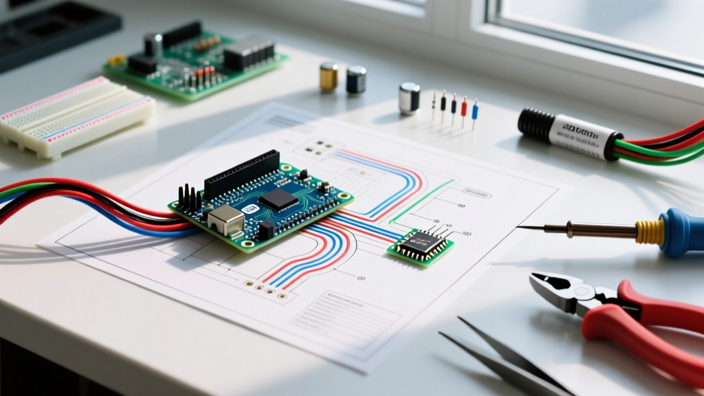

Decoding the Anatomy of a Sample Electrical Wiring Diagram
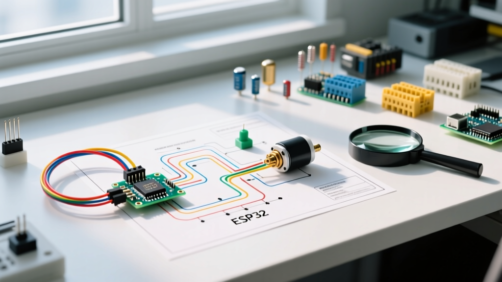
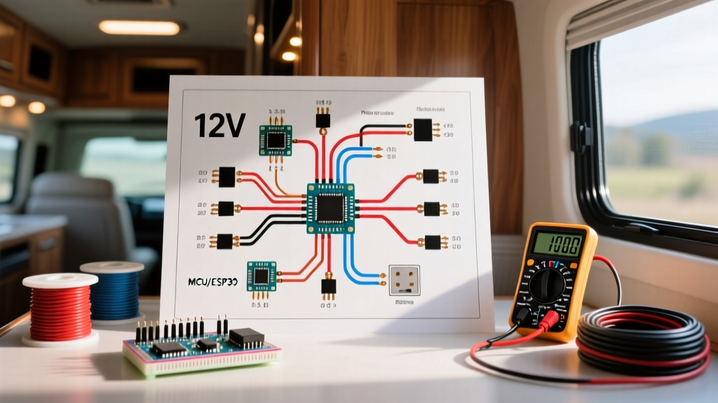
When an electrical system fails, guessing which component is at fault is a costly and dangerous game. A sample electrical wiring diagram serves as your definitive roadmap, translating physical chaos into logical sequences. However, not all diagrams are created equal. Before you pick up a multimeter, you must distinguish between a pictorial wiring diagram (which shows physical wire routing and terminal block locations) and a ladder schematic (which illustrates the logical flow of current). For systematic troubleshooting, the ladder schematic is vastly superior because it isolates the control logic from the high-amperage power circuits.
Most North American industrial and commercial diagrams adhere to NEMA (National Electrical Manufacturers Association) standards, while European and modern HVAC schematics often blend in IEC (International Electrotechnical Commission) symbols. Misinterpreting a normally-open (NO) relay contact as a normally-closed (NC) one due to symbol confusion is a leading cause of misdiagnosis.
Standard Schematic Symbols and Their Diagnostic Meanings
| Component | NEMA Symbol | IEC Symbol | Troubleshooting Function |
|---|---|---|---|
| Limit Switch | NO/NC with a wedge bumper | Square with a diagonal line | Verify mechanical actuation and contact continuity. |
| Contactor Coil | Circle with 'M' or 'C' | Rectangle with diagonal lines | Measure coil resistance; check for open windings. |
| Thermal Overload | Back-to-back semicircles | Rectangle with a thermal curve | Test for tripped state; measure amp draw vs. FLA rating. |
| Capacitor | Parallel lines (one curved) | Parallel straight lines | Discharge safely; test microfarad (MFD) rating. |
The 4-Step Schematic Troubleshooting Workflow
Effective diagnostics require a rigid methodology. According to Fluke's motor troubleshooting methodology, dividing the circuit into logical halves dramatically reduces testing time. Follow this workflow whenever you are analyzing a sample electrical wiring diagram.
Step 1: Lockout/Tagout (LOTO) and Visual Inspection
Before taking a single measurement, isolate the power. Adhering to OSHA's Control of Hazardous Energy guidelines is non-negotiable. Once the disconnect is locked out, perform a visual inspection. Look for melted wire insulation, pitted contactor contacts, or bulging capacitors. A wiring diagram will tell you what should be there; your eyes will tell you what failed catastrophically.
Step 2: Divide and Conquer (Power vs. Control)
Use your sample electrical wiring diagram to identify the boundary between the power circuit (usually 240V/480V) and the control circuit (usually 24V). If the control circuit is dead, the power circuit will never engage. Always troubleshoot the low-voltage control logic first. It is safer, and a blown 24V transformer fuse is a far more common failure point than a shorted compressor winding.
Step 3: Point-to-Point Voltage Testing (Live Circuit)
Once you have verified the control circuit and restored power for live testing, use a True-RMS Digital Multimeter (DMM). Follow the rungs of the ladder diagram from left (L1) to right (L2). Measure the voltage drop across every switch, relay contact, and safety interlock. In a healthy 24V control circuit, you should read 0V across a closed switch and 24V across an open switch or an energized coil.
Step 4: Component Isolation (Dead Circuit)
If you locate a suspect component via live voltage testing, power down, apply LOTO, and switch your DMM to resistance (Ohms) or continuity mode. A healthy contactor coil (e.g., an Eaton C25DND230A) typically reads between 10 and 50 ohms. An infinite reading (OL) confirms an open internal winding, necessitating replacement.
Real-World Scenario: Troubleshooting a 240V HVAC Compressor Circuit
Let us apply a sample electrical wiring diagram to a common real-world failure: a residential 3-ton HVAC condenser unit where the fan runs, but the compressor hums and trips the 30A breaker.
The Setup: The circuit utilizes 10 AWG THHN copper wire, a 30A double-pole breaker, a 24V control circuit feeding an Eaton definite-purpose contactor, and a 45/5 MFD 370VAC dual run capacitor.
- Consulting the Diagram: The sample electrical wiring diagram shows the 24V thermostat signal energizing the contactor coil, which pulls in the high-voltage contacts to send 240V to the compressor's 'C' (Common) and 'R' (Run) terminals. The 'S' (Start) terminal is routed through the run capacitor.
- The Voltage Test: With the system calling for cooling, you measure 240V at the line side of the contactor, and 240V at the load side. The contactor is functioning. You then measure voltage at the compressor terminals: 240V across C and R, and 240V across C and S. Power is reaching the hermetic seal.
- The Capacitor Test: The diagram routes the start winding through the 45 MFD section of the dual capacitor. You power down, discharge the capacitor with a 20k-ohm 5-watt resistor, and test it with a dedicated capacitance meter. The meter reads 12 MFD on the compressor side. Diagnosis: The capacitor has degraded severely (below the NEC-allowed 10% tolerance threshold), starving the start winding of the phase-shifted current needed to generate starting torque.
- Winding Verification: To ensure the compressor motor is not internally shorted, you measure the winding resistance. The rule of thumb dictated by the diagram's motor specs is: Resistance (C to R) + Resistance (C to S) = Resistance (R to S). If your readings are 1.5Ω, 3.0Ω, and 4.5Ω respectively, the windings are intact. Replace the $35 capacitor, and the system is restored.
Common Pitfalls When Interpreting Sample Diagrams
Expert Warning: The Ghost Voltage Trap
When using a high-impedance DMM (like a Fluke 87V) on long, unshielded control wires shown in your sample electrical wiring diagram, you may read 40V to 60V on a disconnected wire. This is induced electromagnetic interference (EMI) or 'ghost voltage' from adjacent energized conductors. Always use a low-impedance (LoZ) setting or a solenoid voltage tester to confirm true voltage presence before condemning a component.
- Ignoring Wire Gauge and Routing Notes: A diagram often includes a bill of materials or marginal notes specifying wire types (e.g., 18 AWG shielded for sensor lines). Replacing a shielded sensor wire with standard unshielded THHN can introduce noise that causes microcontroller logic faults.
- Misreading Ladder Logic Rungs: Current flows from L1 (left) to L2 (right). A common mistake is assuming components drawn in parallel on the diagram are wired in parallel physically. Always trace the node numbers (e.g., Wire #42 connects to all components labeled '42').
- Overlooking Interlocks: Modern sample diagrams include solid-state interlocks, phase monitors, and pressure switches. If a high-pressure switch is wired in series with the contactor coil, a refrigerant overcharge will prevent the contactor from pulling in, mimicking a dead control circuit.
Essential Diagnostic Tools for Schematic-Based Troubleshooting
To effectively execute the tests derived from your sample electrical wiring diagram, you need precision instruments. Here is the 2026 baseline toolkit for serious electrical diagnostics:
- Fluke 87V Industrial True-RMS Multimeter ($480 - $520): The industry standard. Its LoZ (Low Impedance) mode is critical for eliminating ghost voltages on control circuits, and its built-in thermometer allows for simultaneous thermal and electrical checks on breaker panels.
- Megger MIT485/2 Insulation Tester ($1,100 - $1,300): When a diagram indicates a motor or long underground cable run, a standard DMM's 9V battery cannot detect degrading insulation. The Megger injects up to 1000V to measure insulation resistance in Megohms, predicting failures before they cause dead shorts.
- Fieldpiece SC260 Clamp Meter ($250 - $280): Essential for verifying the amperage draw against the Full Load Amps (FLA) listed on the component's nameplate and the diagram's overload settings.
Frequently Asked Questions (FAQ)
Why does the physical wiring not match the sample electrical wiring diagram?
Field modifications are common in older systems. Previous technicians may have bypassed safety interlocks, replaced OEM control boards with universal 'shoe-string' boards, or altered transformer tap settings. Always treat the diagram as a baseline, but trust your live voltage measurements and physical wire tracing over the paper document when discrepancies arise.
How do I troubleshoot a circuit if I cannot find the exact sample electrical wiring diagram?
If the OEM schematic is missing, look for the manufacturer's data plate on the main enclosure. You can usually download the PDF schematic from the manufacturer's technical portal using the exact model and serial number. If unavailable, you must reverse-engineer the circuit by identifying the power source, mapping the control transformer, and tracing the wire node numbers using a continuity tester while the system is de-energized.
What does a dashed line between components on a wiring diagram mean?
In standard NEMA and IEC schematics, a dashed or dotted line connecting multiple switches or contacts indicates mechanical interlocking or simultaneous actuation. For example, if a dashed line connects a NO and NC contact, it means they are part of the same physical relay block; when the coil energizes, both contacts change state at the exact same millisecond.
Mastering the interpretation of a sample electrical wiring diagram transforms troubleshooting from a frustrating guessing game into a precise, scientific process. By combining schematic literacy with methodical DMM testing and adherence to NFPA 70 National Electrical Code safety standards, you can diagnose and resolve complex electrical faults safely and efficiently.