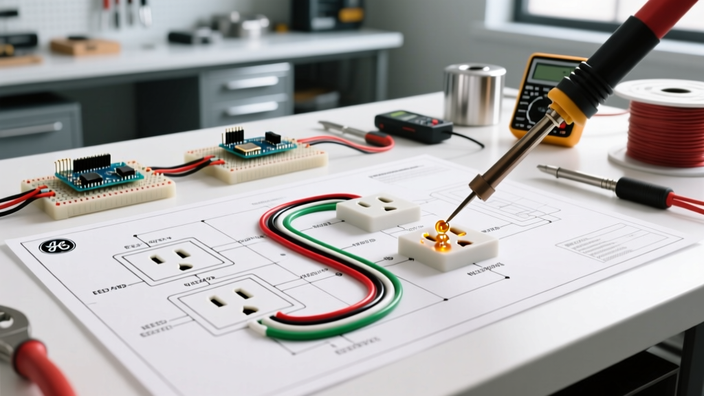

Understanding the Wiring Diagram for a EZGO Golf Cart
Interpreting a wiring diagram for a EZGO golf cart requires more than just tracing colored lines; it demands a rigorous understanding of electrical safety, overcurrent protection, and code compliance. Whether you are maintaining a legacy 36V DC TXT model or upgrading a modern 48V AC RXV, the electrical architecture involves high-amperage direct current (DC) that poses severe fire and arc-flash risks if improperly configured. In 2026, with the proliferation of high-speed aftermarket motors and lithium-ion battery conversions, adhering to established safety protocols is non-negotiable.
The primary architectures for EZGO carts are the series-wound DC systems (found in older TXT models) and the separately excited (SepEx) or AC induction systems (found in newer TXT and RXV models). A standard wiring diagram will route power from the battery pack through a main solenoid (contactor), into the motor controller (such as the Curtis 1206 or 1236), and finally to the drive motor. Misinterpreting these diagrams often leads to catastrophic component failure, which is why we must view the schematic through the lens of the National Electrical Code (NEC) and rigorous safety standards.
NEC Code Compliance and Battery Standards
While golf carts are not typically subject to the same rigorous building inspections as residential wiring, the principles of the NFPA 70 (National Electrical Code) still apply, particularly regarding overcurrent protection and battery installations. NEC Article 480 governs storage batteries, mandating proper ventilation, terminal insulation, and overcurrent protection for battery banks. Furthermore, when installing charging receptacles, NEC Article 625 (Electric Vehicle Charging System Equipment) dictates the use of Ground Fault Circuit Interrupter (GFCI) protection for the AC supply side.
Wire Gauge and Amperage Matrix
Selecting the correct American Wire Gauge (AWG) is critical to preventing voltage drop and thermal melting of insulation. The following table outlines the minimum requirements based on standard EZGO configurations and continuous draw limits:
| System Architecture | Max Continuous Draw | Min. Main Cable Gauge | Recommended ANL Fuse | Estimated Cable Cost (2026) |
|---|---|---|---|---|
| 36V DC (TXT Series) | 120A - 150A | 2 AWG | 150A - 200A | $45 - $65 |
| 48V DC (TXT SepEx) | 150A - 180A | 2 AWG or 1 AWG | 200A - 250A | $55 - $80 |
| 48V AC (RXV) | 200A - 275A | 1 AWG or 1/0 AWG | 250A - 300A | $75 - $110 |
Note: Always use pure copper, welding-grade flexible cable. Copper-clad aluminum (CCA) wire is strictly prohibited for high-draw DC traction applications due to its higher resistance and susceptibility to galvanic corrosion at the lugs.
Solenoid Wiring and Pre-Charge Circuit Safety
The most common point of catastrophic failure in an EZGO wiring diagram is the main solenoid. The solenoid acts as a heavy-duty relay, connecting the high-current battery pack to the controller. When the solenoid closes, the controller's internal capacitors act as a dead short until they are fully charged. Without a pre-charge resistor, the massive inrush current (often exceeding 800A for a fraction of a second) will instantly weld the solenoid's internal contacts together. If this happens, the cart will become a runaway vehicle, unable to be shut off via the key switch.
Pre-Charge Resistor Specifications
- 36V Systems: Require a 470-ohm, 2-watt power resistor wired across the main solenoid's large terminals.
- 48V Systems: Require a 250-ohm, 5-watt power resistor wired across the main solenoid's large terminals.
These resistors cost between $8 and $12 but save you from replacing a $450+ Curtis controller or dealing with a severe safety hazard. Never bypass the pre-charge circuit to 'save time' during a wiring repair.
Overcurrent Protection and Terminal Torque
According to OSHA electrical safety guidelines, all ungrounded conductors must be protected by an overcurrent device rated for the ampacity of the wire. In EZGO carts, this is achieved using an ANL fuse or a marine-grade DC circuit breaker mounted within 18 inches of the main battery positive terminal.
The Danger of Improper Torque
A frequently overlooked aspect of the wiring diagram execution is hardware torque. Battery lugs on 6V and 8V deep-cycle lead-acid batteries require exactly 110 in-lbs (9.2 ft-lbs) of torque.
Expert Insight: Under-torquing battery terminals creates microscopic air gaps. Under heavy load, these gaps cause micro-arcing, which generates extreme localized heat, melts the lead post, and can ignite hydrogen gas emitted during the charging cycle. Over-torquing strips the soft lead threads, resulting in the exact same failure mode. Always use a calibrated inch-pound torque wrench.
Charging Circuit Compliance and Receptacle Wiring
The AC side of the EZGO wiring diagram involves the onboard charger and the charging receptacle. Older models use a 3-pin 'Powerwise' D-plug, while newer RXV models use a 4-pin or 5-pin serial-communicating receptacle. When replacing or wiring a new charging circuit, you must ensure the AC supply side complies with modern safety standards.
If you are installing a dedicated 120V outlet in your garage specifically for charging the golf cart, NEC Article 625.54 requires GFCI protection for all 125-volt and 250-volt receptacles rated at 50 amperes or less that supply EV charging equipment. Installing a high-quality GFCI receptacle (such as the Leviton GFNT2-W, priced around $25-$35) or a GFCI breaker prevents lethal shock hazards in damp garage environments. Furthermore, ensure the charger's AC ground wire is securely bonded to the receptacle's grounding pin; never float the ground on a Class I appliance.
Step-by-Step Safety Verification Protocol
Before applying full power after executing any wiring diagram modifications, follow this strict verification protocol to prevent short circuits and component destruction:
- Visual Inspection: Verify all wire routing avoids sharp metal edges, steering columns, and moving suspension parts. Ensure all cable looms are secured with UV-resistant zip ties every 12 inches.
- Continuity Check (Power Off): Using a digital multimeter (DMM) in continuity mode, verify there is no short between the main positive bus and the cart's chassis ground.
- Voltage Verification (Pack Side): Connect the main battery pack. Measure the voltage at the solenoid's battery-side terminal. It should read within 0.5V of the total pack voltage (e.g., 50.4V for a fully charged 48V lead-acid pack).
- Key-On Solenoid Test: Turn the key to the 'ON' position and press the accelerator slightly. You should hear a distinct, sharp 'click' from the solenoid. Measure the voltage on the controller-side terminal of the solenoid; it must match the pack voltage.
- Thermal Imaging (Under Load): After a 10-minute test drive, use a thermal camera or infrared thermometer to scan all battery terminals, the solenoid, and the controller bus bars. Any connection exceeding 120°F (49°C) indicates a high-resistance joint that must be cleaned, re-crimped, and re-torqued immediately.
Authoritative References and Further Reading
To ensure your modifications remain safe and legally compliant, always consult the latest industry standards and manufacturer documentation. The following resources provide the foundational safety codes referenced in this guide:
- NFPA 70: National Electrical Code (NEC) - Essential for understanding Articles 480 (Storage Batteries) and 625 (EV Charging).
- OSHA Electrical Safety Standards - Guidelines for overcurrent protection and workplace electrical safety.
- Battery Council International (BCI) Handling Safety - Best practices for lead-acid and lithium battery terminal maintenance and ventilation.
By treating the wiring diagram for a EZGO golf cart as a critical safety document rather than a simple suggestion, you ensure the longevity of your vehicle's electrical system and, more importantly, the physical safety of its passengers.