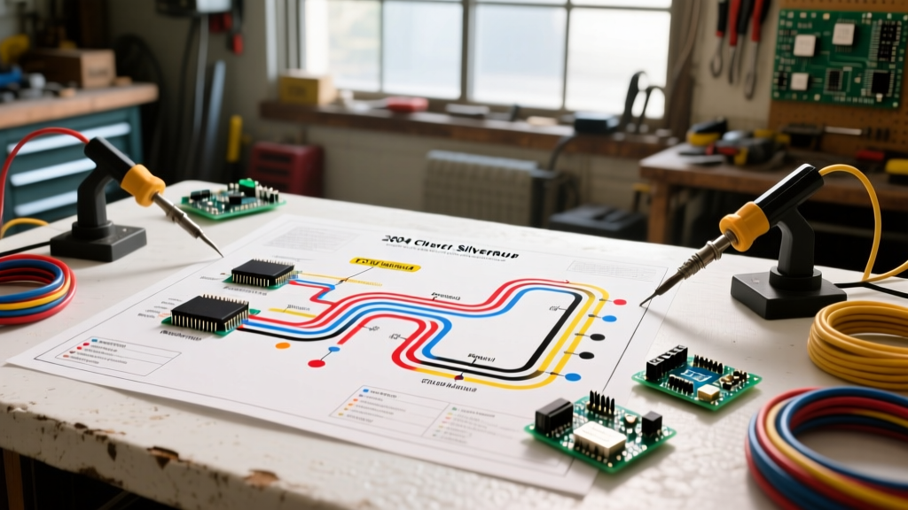

Navigating the GMT800 Electrical Architecture
As of 2026, the 2004 Chevrolet Silverado—a hallmark of the legendary GMT800 platform—is over two decades old. While the 5.3L Vortec V8 (RPO LM7/L59) is renowned for its mechanical longevity, the electrical system requires meticulous attention. The cross-linked polyethylene (XLPE) wire insulation used by General Motors is highly resistant to heat and chemicals, but after 22 years of thermal cycling, harnesses routed near exhaust manifolds and the firewall become brittle. Understanding the wiring diagram for a 2004 Chevy Silverado is no longer just about tracing circuits; it is about identifying age-related failure modes, high-resistance ground faults, and module communication breakdowns.
This reference guide bypasses generic overviews and dives directly into the critical pinouts, ground matrices, and specific troubleshooting procedures required to keep a 2004 Silverado running flawlessly.
Powertrain Control Module (PCM) Pinout Highlights
The 2004 Silverado utilizes a single PCM located in the engine bay on the driver's side, behind the battery and air intake resonator. For the ubiquitous 5.3L V8, the PCM interfaces with the engine and transmission harnesses via three primary Delphi connectors:
- Connector C1 (Blue, 80-Way): Handles primary power, grounds, and injector control.
- Connector C2 (Red, 80-Way): Manages sensor inputs (MAF, TPS, O2 sensors) and Class 2 serial data.
- Connector C3 (Black, 40-Way): Dedicated primarily to the 4L60-E transmission solenoids and vehicle speed sensors.
Critical PCM Circuit References
| Connector | Pin | Wire Color | Circuit Function | Diagnostic Note |
|---|---|---|---|---|
| C1 (Blue) | 1, 2 | Red | Battery Positive (Ignition 1) | Verify >12.2V with engine off. Voltage drop indicates corroded underhood fuse block feed. |
| C1 (Blue) | 40, 41 | Black/White | PCM Power Ground | Must read <0.05V drop to battery negative. High resistance causes random injector misfires. |
| C2 (Red) | 21 | Orange | Class 2 Serial Data | Communicates with BCM and ABS. If dead, OBD2 scanner will not link. |
| C2 (Red) | 66 | Light Blue | 4X Low Speed Reference (Crank) | Verify 5V square wave with oscilloscope during cranking. No signal = P0335 code. |
The Achilles Heel: Ground Point Matrices
According to decades of technical service bulletins tracked by the National Highway Traffic Safety Administration (NHTSA), poor grounding is the number one cause of phantom electrical gremlins in the GMT800 platform. The 2004 Silverado relies on several critical chassis grounds that are prone to galvanic corrosion between the copper ring terminal and the aluminum/cast-iron mating surface.
G110: The Engine Block Ground
Located at the left rear of the engine block, near the cylinder head, G110 is the most notorious ground on the 5.3L Vortec. When this ground degrades, the PCM loses its reference for the ignition coils and fuel injectors.
Symptom Profile: P0300 (Random Misfire), erratic tachometer needle, and StabiliTrak/ABS warning lights illuminating simultaneously.
Repair Protocol: Do not simply tighten the bolt. Remove the 10mm bolt, clean the block surface with a 3M Scotch-Brite pad, and clean the ring terminal with fine sandpaper. Apply a thin layer of dielectric grease to prevent future oxidation, and torque the bolt to exactly 18 lb-ft to prevent stripping the cast-iron threads.
G240: The BCM & Instrument Panel Ground
Located under the driver's side door sill, beneath the carpet. G240 grounds the Body Control Module (BCM), power windows, and the Driver Information Center (DIC). Water intrusion from degraded door seals often pools here, causing severe copper oxidation.
2004 Silverado Fuse Block & Relay Matrix
The Underhood Electrical Center (UEC) houses the high-amperage fuses and primary relays. Below is a reference for the most commonly serviced circuits during heavy-duty or towing modifications.
| Fuse / Relay Name | Rating | Circuit Protected | Common Upgrade / Failure Mode |
|---|---|---|---|
| IGN A | 40A | PCM, Ignition Switch Feed | Fails if aftermarket off-road lights are spliced into the ignition run circuit. |
| VEC B | 30A | Engine Cooling Fan Relay | Blows when the fan clutch seizes or the electric auxiliary fan motor shorts internally. |
| SEO B1 | 30A | Upfitter / Auxiliary Power | Used for snow plow prep or winch solenoid feeds. Ensure proper gauge wire (min 10 AWG). |
| HVAC | 30A | Blower Motor Control Module | Frequently blows due to blower motor bearing drag drawing excessive amperage (>25A). |
Step-by-Step Troubleshooting: Passlock II Security System
The 2004 Silverado utilizes the Passlock II anti-theft system. Unlike older VATS systems that used a resistor chip in the key, Passlock II uses a Hall-effect sensor located inside the steering column's ignition lock cylinder. The sensor reads a magnet on the lock cylinder and sends a voltage signal to the BCM.
Passlock II Wiring Colors & Pinout
- Yellow/Black: Low Reference (Ground)
- White: Security Signal to BCM
- Red/White: 5-Volt Reference from BCM
Failure Mode: If the signal wire (White) experiences a voltage drop or the sensor fails, the BCM interprets this as a hot-wire attempt and disables the fuel injectors. The truck will start and immediately stall, accompanied by a flashing 'Security' light on the dash.
The 10-Minute Passlock Relearn Procedure
- Turn the ignition to the ON/RUN position (do not crank the engine).
- Observe the 'Security' light on the instrument cluster. It will remain illuminated.
- Leave the key in the ON position for exactly 10 to 12 minutes until the 'Security' light turns OFF.
- Turn the ignition to OFF and wait 10 seconds.
- Repeat this cycle two more times (three cycles total, roughly 30-35 minutes).
- On the fourth attempt, crank the engine. The BCM has now relearned the new voltage signature from the Passlock sensor.
HVAC Blower Motor Resistor & Pigtail Degradation
A highly prevalent issue in the 2004 Silverado is the melting of the HVAC blower motor resistor pigtail. The resistor block, located under the passenger side dash near the blower motor, regulates fan speeds 1 through 4 via a series of resistors. Speed 5 bypasses the resistor entirely via a high-current relay.
Because the blower motor draws continuous high current (often 15A to 18A) and the factory terminals lack sufficient surface area, the heat generated melts the plastic connector housing. When replacing the resistor block (OEM Part# ACDelco 15-80644), you must also replace the pigtail connector (ACDelco PT2255). Splicing in the new pigtail requires high-quality adhesive-lined heat shrink and crimping. Soldering is not recommended in this high-vibration, high-heat zone, as solder joints can fatigue and crack over time.
Wire Gauge & Splicing Standards for GMT800 Repairs
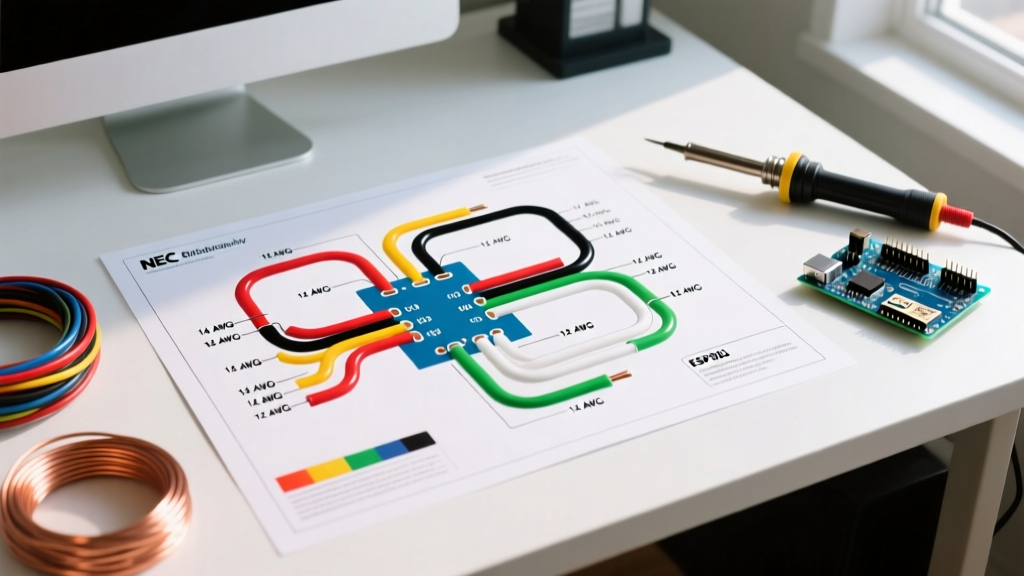
When repairing damaged harnesses on the 2004 Silverado, never use standard PVC household wire or generic electrical tape. Automotive environments require wire that can withstand 125°C continuous heat and exposure to oil and transmission fluid.
According to automotive wiring standards outlined by SAE International (specifically SAE J1128 and ISO 6722-1), you should exclusively use GXL or TXL thin-wall automotive wire. GXL wire features cross-linked polyethylene insulation, allowing for a thinner outer diameter without sacrificing thermal protection, making it ideal for routing through the Silverado's tightly packed firewall grommets.
Best Practices for Harness Repair
- Crimping over Soldering: Use OEM-style open-barrel crimp sleeves with a proper ratcheting crimper. Solder wicks into the wire strands and creates a rigid point that will snap under engine vibration.
- Sealing: Use dual-wall (adhesive-lined) polyolefin heat shrink tubing. When heated, the inner lining melts and seals out moisture, preventing the green copper oxide corrosion that plagues GMT800 sensor circuits.
- Loom Protection: Always re-wrap repaired harness sections in split-loom tubing and secure with Tesa 51036 PET cloth tape. This prevents the harness from chafing against the sharp edges of the aluminum intake manifold or steel frame rails.
Final Diagnostic Takeaways
Troubleshooting the 2004 Chevy Silverado wiring diagram requires a shift in mindset. You are not just looking for broken wires; you are looking for micro-corrosion, terminal fretting, and ground degradation. By focusing your multimeter diagnostics on the PCM ground circuits, maintaining the Passlock II signal integrity, and upgrading the HVAC high-current pigtails with modern ACDelco components, you can ensure this GMT800 platform remains as reliable electrically as it is mechanically.