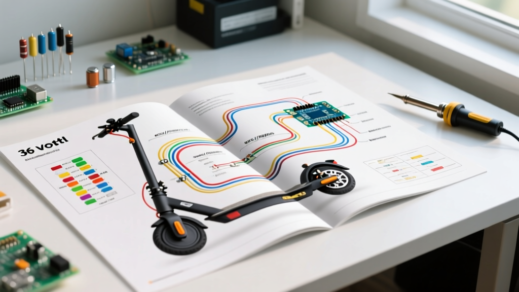

Decoding the 36 Volt Electric Scooter Wiring Diagram PDF
Transitioning from a stock ride to a custom 36V electric scooter build in 2026 requires more than just bolting on a new motor; it demands a rigorous understanding of direct current (DC) architecture. Whether you are upgrading a classic Razor E300 platform, building a wooden deck commuter, or repairing a generic 350W brushless hub motor system, the foundational blueprint for your build is the 36 volt electric scooter wiring diagram PDF. These schematics map the critical pathways between your energy storage, motor controller, and user inputs. However, reading these diagrams is only the first step. Proper installation planning dictates wire gauge selection, connector selection, and fail-safe routing to prevent catastrophic thermal events.
In this installation planning guide, we dissect the standard 36V DC topology, outline exact wire gauge requirements based on continuous amperage, and provide a step-by-step execution plan to ensure your controller, battery management system (BMS), and hall-effect sensors communicate flawlessly.
Core Components in a Standard 36V Architecture
Before executing the physical wiring, you must verify that your components match the schematic's assumptions. A nominal 36V system actually operates between 30.0V (fully depleted) and 42.0V (fully charged) when utilizing a 10-series (10S) Lithium-Ion configuration. If your diagram assumes a 3x12V Sealed Lead Acid (SLA) setup, the voltage curve and peak amperage draws will differ significantly.
1. The Motor Controller
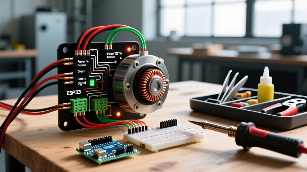
For brushed motors, the YK31C-3 or similar 36V 15A controllers remain the industry standard for DIY replacements. For brushless DC (BLDC) hub motors, you will likely use a 36V 350W square-wave or sine-wave controller (such as the KT36/24SVPR series). The wiring diagram PDF for BLDC controllers is inherently more complex due to the inclusion of 3-phase motor wires and 5-pin Hall sensor feedback loops.
2. Energy Storage and BMS
Modern 2026 builds heavily favor 21700 cylindrical cells (like the Molicel P45T) over older 18650 formats, allowing for compact 10S4P packs that deliver 18Ah+ capacity. According to Battery University, managing series and parallel configurations requires a robust BMS to monitor individual cell group voltages and prevent over-discharge. Your wiring diagram must explicitly show the BMS balance leads and the main charge/discharge pathways (B-, P-, and C- pads).
⚠️ Critical Safety Warning: Never bypass the BMS discharge circuit to wire the controller directly to the battery's raw positive and negative terminals. In the event of a controller MOSFET failure, a direct connection will result in an uncontrolled short circuit, leading to immediate thermal runaway. Always route the main negative through the BMS P- (Discharge) pad.
Pre-Installation Planning: Wire Gauge & Routing
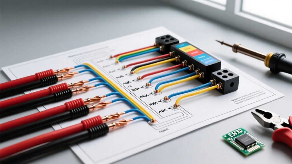
The most common point of failure in DIY scooter builds is undersized wiring, which leads to voltage sag, melted insulation, and connector fires. When interpreting your 36 volt electric scooter wiring diagram PDF, you must assign the correct American Wire Gauge (AWG) to each circuit based on the maximum continuous current draw. Utilizing the DC circuit principles outlined by Blue Sea Systems, we calculate gauge requirements factoring in a 10% voltage drop allowance over standard scooter harness lengths (under 3 feet).
| Circuit Application | Max Continuous Amps | Recommended AWG | Connector Type |
|---|---|---|---|
| Battery to BMS / Main Loop | 25A - 35A | 10 AWG Silicone | Amass XT90-S (Anti-Spark) |
| Controller to Motor Phases | 20A - 30A | 12 AWG Silicone | 4mm Bullet Connectors |
| Main Ignition / Key Switch | 2A - 5A | 16 AWG Stranded | Spade Terminals / JST |
| Throttle & Hall Sensors | < 0.5A | 18-20 AWG Stranded | JST-SM 3-Pin / 5-Pin |
| Brake Cut-off Switches | < 0.5A | 20 AWG Stranded | JST-SM 2-Pin |
Pro-Tip: Always use silicone-jacketed wire for high-current phase and battery lines. Standard PVC-jacketed wire becomes brittle under the vibration of a scooter deck and will melt if the controller experiences a brief current spike exceeding 40A during hill climbs.
Step-by-Step Controller Pinout Execution
With your materials staged, follow this sequential wiring order. Deviating from this sequence—particularly by connecting logic wires before main power grounds—can result in ground-loop feedback that fries the controller's 5V voltage regulator.
Step 1: The Main Power Loop
- Solder 10 AWG red and black wires to your BMS P+ and P- pads.
- Route the main negative (black) directly to the controller's thick black battery wire.
- Install an Amass XT90-S anti-spark connector on the positive line. The integrated resistor prevents the massive inrush current from arcing and pitting your controller's capacitors upon connection.
- Wire the main positive (red) through your deck's safety kill-switch, then to the controller's thick red battery wire.
Step 2: The Ignition / Logic Wake-Up
Most 36V controllers feature a thin red wire (often labeled 'Lock' or 'Ignition'). This wire must receive 36V+ to wake up the controller's internal logic board. Splice this thin red wire into the main positive line after the key switch. When you turn the key, it sends voltage to the logic board, which then closes the main internal MOSFETs to power the motor.
Step 3: Motor Phases and Hall Sensors
For BLDC motors, connect the three thick phase wires (Yellow, Green, Blue) using 4mm bullet connectors. Ensure they are fully seated; a loose phase connection will cause severe arcing, melting the connector and potentially destroying the controller's MOSFET bridge. Next, plug in the 5-pin Hall sensor connector. Verify the pinout using your specific wiring diagram PDF, as the 5V logic line (usually red) and ground (usually black) can sometimes be reversed on generic replacement motors.
Step 4: Throttle and Brake Integration
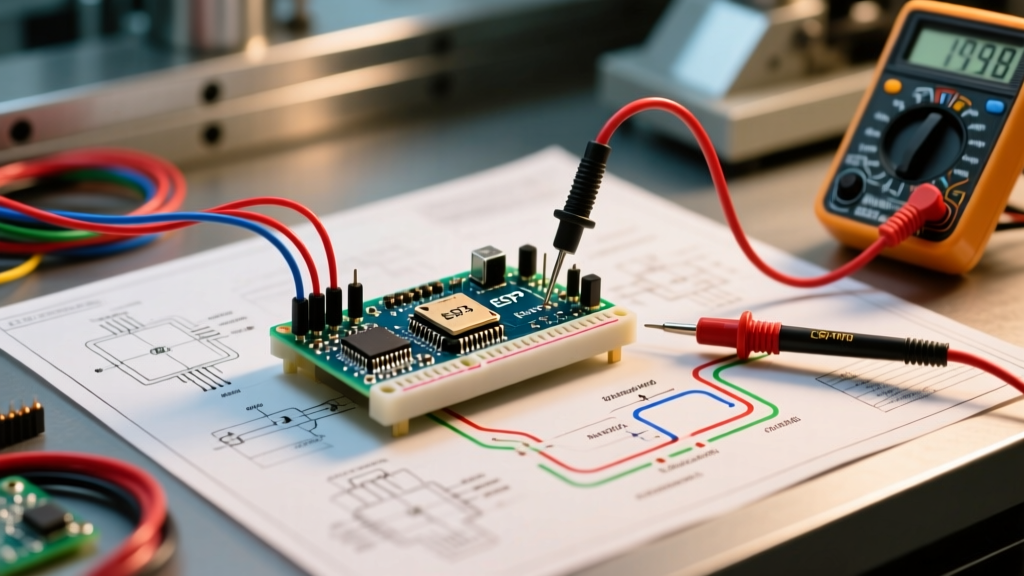
Connect the 3-pin hall-effect throttle. Use a multimeter to verify the 5V output from the controller's red throttle wire before plugging in the throttle unit. The signal wire should read 0.8V at rest and sweep smoothly to 4.2V at full twist. Wire the normally-closed (NC) brake cut-off switches in parallel to the controller's brake inhibit pins.
Common Failure Modes & Troubleshooting Edge Cases
Even with a perfect 36 volt electric scooter wiring diagram PDF, physical installation introduces variables that can cause system failures. Here are the most common edge cases encountered in the field:
- The "Magic Smoke" Hall Sensor Failure: If the 5V hall sensor wire accidentally shorts to the 36V main positive line (often due to chafing inside the motor axle), it will instantly send 42V back into the controller's 5V logic rail, destroying the microcontroller. Solution: Always route low-voltage sensor wires on the opposite side of the fork/deck from high-current phase wires, and use spiral cable wrap for abrasion resistance.
- Controller Over-Voltage Protection (OVP) Trips: If you are using a 36V controller but charging a 10S pack to 42.0V, some overly sensitive generic controllers will trigger OVP and refuse to arm. Solution: Adjust your BMS max charge voltage to 41.5V or flash the controller firmware to raise the OVP threshold to 44V.
- Throttle Signal Bounce: If the scooter accelerates erratically without user input, you likely have voltage drop on the 5V logic line due to undersized ground wires. Solution: Solder a dedicated 18 AWG ground wire directly from the controller's logic ground to the throttle's ground pin, bypassing the thin harness wires.
Safety Standards and Final Validation
As electric micromobility devices face increased scrutiny, adhering to safety standards is paramount. The U.S. Consumer Product Safety Commission (CPSC) heavily emphasizes the dangers of improper battery wiring and the necessity of UL-certified components to prevent fires. Ensure your 10S BMS is equipped with over-temperature thermistors taped directly to the battery cells, and verify that all high-current solder joints are insulated with adhesive-lined heat shrink tubing to prevent moisture ingress and short circuits.
Before your first test ride, perform a "bench test." Elevate the rear wheel, connect the battery, and slowly roll the throttle. Monitor the temperature of the XT90 connector and the controller casing. If the wiring diagram was followed precisely, and the gauge selections were respected, your 36V system will deliver reliable, efficient torque for thousands of miles.