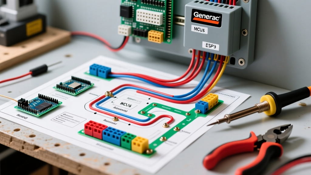

Adapting the Wiring Diagram for Generac Automatic Transfer Switch to Mobile Platforms
Integrating a backup power system into a Class A motorhome, custom expedition truck, or mobile medical command center requires a fundamental shift from residential wiring paradigms. When sourcing the wiring diagram for Generac automatic transfer switch units, most available documentation assumes a static, climate-controlled home environment. However, mobile applications introduce high-frequency vibration, extreme thermal cycling, and complex inverter-charger interactions. This guide bridges the gap between Generac’s official schematics and the rigorous demands of vehicle-specific electrical builds, focusing on the widely used Generac 50-Amp RV ATS (Model RTSW050A3) and the 100-Amp Service Rated ATS (Model RTSD100A3) for heavy-duty mobile rigs.
Anatomy of the Generac 50A RV ATS (Model RTSW050A3)
The Generac RTSW050A3 is a voltage-sensing, dual-coil magnetic latch transfer switch designed specifically for 50-amp RV applications. Priced between $210 and $260 in 2026, it remains the industry standard for seamlessly switching between shore power and an onboard diesel or propane generator (such as a Cummins Onan QD series or Generac PrimePower). Unlike home standby switches that utilize a low-voltage DC control wire from the generator controller, the RTSW050A3 relies entirely on AC voltage sensing. When Source 2 (Generator) detects a stable 120/240V output for a preset delay (typically 5 to 10 seconds), the internal solenoids actuate, physically moving the contacts from Source 1 (Shore) to Source 2.
Source 1 (Shore) vs. Source 2 (Generator) Logic
The internal wiring diagram dictates that Source 1 is the 'preferred' source. If shore power is present and within acceptable voltage parameters (usually 104V to 132V per leg), the ATS will remain latched to Source 1, even if the generator is running. Only when Source 1 drops out, or falls outside the acceptable voltage window, will the ATS evaluate Source 2 and execute the transfer. This prioritization logic is critical when wiring the ATS downstream of a smart inverter-charger setup, as inverters can sometimes backfeed voltage that confuses the ATS sensors.
Vehicle-Specific Wiring Matrix: Gauges, Terminals, and Torque
Residential wiring typically utilizes solid copper THHN wire. In a vehicle, solid wire will work-harden and snap due to chassis vibration and road harmonics. You must use Class K fine-strand marine-grade copper wire. Below is the specification matrix for a 50A and 100A mobile ATS installation.
| Parameter | 50A ATS (RTSW050A3) | 100A ATS (RTSD100A3) |
|---|---|---|
| Wire Gauge (Hot/Neutral) | 6 AWG Class K Stranded | 2/0 AWG Class K Stranded |
| Wire Gauge (Ground) | 8 AWG Class K Stranded | 1/0 AWG Class K Stranded |
| Terminal Type | Closed-loop or Pin Ferrule | Heavy-Duty Lugged (3/8" stud) |
| Crimping Tool | Knipex Twin Ferrule / Ratchet | Hydraulic or 1-Ton Mechanical |
| Torque Specification | 45 in-lbs (Inch-Pounds) | 120 in-lbs (10 ft-lbs) |
| Heat Shrink | 3:1 Marine Adhesive-Lined | 3:1 Marine Adhesive-Lined |
The Neutral-Ground Bonding Dilemma in Vehicles
CRITICAL WARNING: Never bond the neutral and ground buses inside the ATS enclosure or the main vehicle sub-panel if the inverter-charger or generator already features an internal automatic neutral-ground relay. Double-bonding creates parallel neutral paths, causing stray currents to flow through the vehicle chassis, which can lead to severe galvanic corrosion or lethal shock hazards.
According to the guidelines established in NFPA 1192 (Standard for Recreational Vehicles), the neutral-to-ground bond must occur at exactly one point in the system—typically at the source (the generator or the inverter when in inversion mode). The wiring diagram for the Generac ATS shows the neutral and ground passing through as isolated conductors. Ensure the ATS ground bus is bonded to the vehicle's main DC chassis ground via a minimum 8 AWG (for 50A) green grounding conductor, but keep the AC neutral completely floating through the switch.
Edge Case: Inverter-Charger Pass-Through and Relay Chatter
A frequent failure mode in high-end expedition vehicles occurs when integrating a Generac ATS with powerful inverter-chargers like the Victron Quattro or Magnum MSH-M series. These devices feature an internal transfer switch that passes shore power through to the vehicle's AC panel. If the Generac ATS is wired upstream of the inverter, the inverter's power-assist or UPS-mode switching can create micro-interruptions or output a modified sine wave during the transfer delay.
The Generac ATS solenoids require a clean, pure sine wave to maintain a stable magnetic latch. If the inverter outputs a modified sine wave or introduces severe Total Harmonic Distortion (THD) during a grid fault, the ATS solenoid may 'chatter' (rapidly open and close), eventually welding the internal contacts shut. To prevent this, wire the ATS downstream of the inverter's AC input, or install an external heavy-duty contactor (like the Schneider Electric TeSys series) triggered by the ATS logic board to handle the physical switching of high-THD loads.
Step-by-Step Mobile Installation Protocol
- Disconnect All Power: Isolate the vehicle’s DC battery bank using the main disconnect switch and unplug shore power. Verify zero voltage with a CAT III multimeter.
- Mounting and Vibration Isolation: Mount the Generac ATS to a structural bulkhead. Use 3M VHB tape or rubber isolation grommets between the ATS enclosure and the metal chassis to dampen high-frequency diesel engine vibrations. Apply Loctite 222 (purple) to all mounting hardware screws to prevent vibrational loosening while allowing future removal.
- Prepare Conductors: Strip 6 AWG (or 2/0 AWG) Class K wire. Apply adhesive-lined heat shrink before crimping. Use a ratcheting crimper to ensure a gas-tight connection.
- Wire Source 1 and Source 2: Follow the Generac schematic exactly. Source 1 (Shore/Inverter Output) connects to the top terminal block. Source 2 (Generator) connects to the bottom terminal block. Do not reverse these, or the ATS will default to the generator even when shore power is available.
- Torque and Verify: Use a calibrated inch-pound torque screwdriver to tighten all terminal block screws to 45 in-lbs. Tug-test every wire.
- Test Sequence: Reconnect DC power. Start the generator without shore power connected. Verify the ATS transfers to Source 2 within 10 seconds. Plug in shore power; verify the ATS transfers back to Source 1 within 3 seconds.
Troubleshooting Common ATS Failures in High-Vibration Environments
- Symptom: ATS hums loudly but does not transfer.
Diagnosis: Voltage drop on the Source 2 sensing lines. The generator may be producing 110V at the stator, but a poor connection at the generator's junction box drops it to 102V by the time it reaches the ATS. The ATS low-voltage cutoff prevents the transfer to protect vehicle appliances. - Symptom: Transfer switch works, but GFCI outlets in the vehicle trip immediately.
Diagnosis: Neutral-Ground fault. The neutral wire insulation may have been pinched against the metal ATS enclosure during installation, or a double-bond exists downstream. Isolate the neutral bus and perform a megger test. - Symptom: ATS is completely dead; no clicking sound when generator starts.
Diagnosis: Blown internal logic fuse or failed DC control relay. While the RTSW050A3 is primarily AC sensed, some custom mobile integrations use a 12V DC trigger wire to force the switch. Check the inline automotive blade fuse on the 12V trigger circuit.
For official schematics and updated firmware logic boards, always cross-reference the Generac Support Manuals portal using your specific serial number. Furthermore, adherence to RVIA electrical standards ensures your mobile installation remains insurable and safe for off-grid operation. By treating the wiring diagram for Generac automatic transfer switch units as a baseline rather than a final rulebook, mobile electricians can build power systems that survive the harshest expedition environments.