
Mastering the Wiring Diagram for 3 Way Switch with Multiple Lights
Wiring a multi-light corridor, staircase, or large workshop bay requires more than just connecting a few wires; it demands a precise understanding of circuit topology, traveler logic, and modern electrical codes. When you need to control three or more light fixtures from two separate locations, the standard single-pole setup falls short. This comprehensive guide breaks down the exact wiring diagram for 3 way switch with multiple lights, addressing both legacy mechanical setups and the strict neutral-wire requirements introduced in recent National Electrical Code (NEC) updates.
Anatomy of a 3-Way Switch: Terminal Identification
Before interpreting any diagram, you must understand the hardware. Using the industry-standard Leviton Decora 5603-2W 15-Amp 3-Way Switch as our reference model, a 3-way switch features four critical connection points:
- Common Terminal (Black/Dark Screw): This is the pivot point. On the line-side switch, it connects to the incoming hot power. On the load-side switch, it connects to the switched hot feeding the lights.
- Traveler Terminals (Two Brass Screws): These carry the alternating current paths between the two switches. The NEC does not mandate specific colors for travelers, but professional electricians typically use red and black (or red and blue) to distinguish them from neutrals.
- Ground Terminal (Green Screw): Connects to the bare copper or green insulated equipment grounding conductor.
The Core Topology: Power at Switch 1, Lights in Series
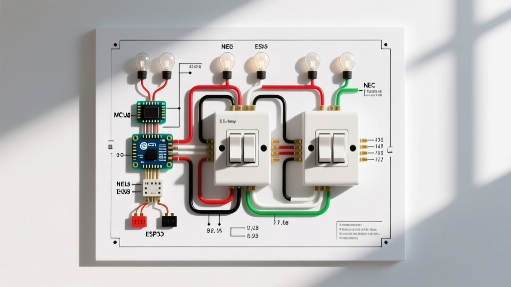
The most common and logical layout for a wiring diagram for 3 way switch with multiple lights places the power source at the first switch, runs the lights in the middle, and terminates at the second switch. However, how you route the cables depends entirely on whether you are following pre-2020 legacy practices or modern NEC Article 404.2(C) compliance.
Legacy Method (Pre-2020 NEC): The /3 Cable Run
In older installations, electricians used 14/3 or 12/3 NM-B (Romex) cable between Switch 1 and the first light fixture. The black wire acted as the common hot, while the red and white (re-identified with black tape) acted as travelers. The lights were daisy-chained using 14/2 cable. Warning: This method does not provide a neutral wire at Switch 2, making it incompatible with modern smart switches or motion sensors.
Modern NEC-Compliant Method: Satisfying Article 404.2(C)
The NFPA 70 (National Electrical Code) now requires a grounded circuit conductor (neutral) at every switch location controlling lighting loads. To achieve this in a multi-light 3-way setup without pulling expensive 4-conductor cable, use the Power-to-First-Light Topology:
- Panel to Light 1: Run 14/2 NM-B (Hot and Neutral arrive at the first light box).
- Light 1 to Switch 1: Run 14/3 NM-B. White = Neutral (pigtailed to Switch 1), Black = Switched Hot (Common), Red = Traveler 1.
- Light 1 to Light 2 (and subsequent lights): Run 14/2 NM-B to daisy-chain the hot and neutral.
- Last Light to Switch 2: Run 14/3 NM-B. White = Neutral, Black = Traveler 1, Red = Traveler 2. Note: The switched hot is routed through the traveler network back to Switch 1.
Pro Tip: Always use a deep 2-gang or 3-gang junction box (minimum 22 cubic inches) at the first light fixture. The convergence of the panel feed, the switch loop, and the daisy-chain to the next light creates a massive wire fill volume that will easily violate NEC Box Fill calculations (Article 314.16) in a standard shallow box.
Wire Gauge, Breaker Sizing, and Material Selection
Selecting the correct wire gauge is non-negotiable for fire safety and preventing voltage drop across long multi-light runs. Refer to the table below for standard residential lighting circuits:
| Circuit Breaker | Wire Gauge (NM-B) | Max Load (Watts @ 120V) | Ideal Wire Nut |
|---|---|---|---|
| 15 Amp | 14 AWG (Solid Copper) | 1,440W (Continuous) | Ideal 341 (Orange) or 332 (Yellow) |
| 20 Amp | 12 AWG (Solid Copper) | 1,920W (Continuous) | Ideal 342 (Yellow) or 345 (Blue) |
Voltage Drop Consideration: If your total cable run from the panel to the furthest light fixture exceeds 50 feet on a 15A circuit, step up to 12 AWG wire to mitigate voltage drop, which can cause LED drivers to flicker or fail prematurely.
Step-by-Step Wiring Procedure
Follow these exact steps to ensure a safe, code-compliant installation. Always verify power is off using a non-contact voltage tester (like the Klein Tools NCVT-2) before opening any junction box.
1. Prepare the Conductors
Strip exactly 3/4 inch of insulation from the end of each solid copper wire. Stripping too little leaves exposed bare wire outside the wire nut; stripping too much leaves bare copper exposed below the nut skirt, creating a short-circuit hazard.
2. Terminate the Grounds
Connect all bare copper ground wires in the box using a green wire nut or a standard crimp sleeve. Run a 6-inch bare copper pigtail from this bundle to the green ground screw on the switch. Torque the ground screw firmly.
3. Manage the Neutrals (Switch Box)
Group all white neutral wires together. If your switch requires a neutral (e.g., smart 3-way switches like the Lutron Caseta PD-6ANS), add a white pigtail to this bundle and connect it to the switch's neutral terminal. Push the neutral bundle deep into the back of the box to save room for the hot wires.
4. Connect Travelers and Common
Connect the two traveler wires (typically red and black from the /3 cable) to the brass screws on the switch. It does not matter which traveler goes to which brass screw; the switch logic will function identically either way. Connect the common wire (the one feeding the lights or coming from the panel hot) to the black/dark common screw.
Troubleshooting Common Failure Modes
Even with a perfect wiring diagram for 3 way switch with multiple lights, mistakes happen. Use this diagnostic matrix to identify edge cases:
- Symptom: Lights only turn on from Switch 1, but Switch 2 does nothing.
Diagnosis: The common wire on Switch 2 is misidentified. You likely connected the switched hot to a brass traveler screw instead of the black common screw. - Symptom: LED lights glow faintly or "ghost" when switched off.
Diagnosis: Capacitive coupling or induced voltage on long parallel traveler runs. Install a Lutron LUT-MLC load compensation capacitor across the first light fixture's hot and neutral to bleed off ghost voltage. - Symptom: Breaker trips immediately upon throwing either switch.
Diagnosis: A shared neutral fault. You have likely mixed neutrals from two different circuits in the light box, or a traveler wire is accidentally grounded against the metal box or bare copper.
Final Safety and Code Compliance Checks
Before closing up the drywall or screwing on the faceplates, perform a final audit. The Electrical Safety Foundation International (ESFI) strongly recommends verifying that all wire nuts are tight by giving each wire a firm tug. No bare copper should be visible outside the nut. Ensure that the switches are perfectly plumb using a torpedo level before tightening the mounting straps, as overtightening can warp the plastic yoke and cause the rocker mechanism to bind. By adhering strictly to these topology rules and NEC guidelines, your multi-light 3-way circuit will provide decades of safe, reliable operation.